Exploring how capacitors store electrical energy involves understanding capacitance and charge. We start with the basic idea of capacitance, which is measured in Farads, and move to more detailed topics like self-capacitance and stray capacitance, including how to manage them. The discussion includes formulas to calculate capacitance in different setups and the importance of dielectric materials. With examples and theory, this guide explains how capacitors charge and discharge, giving a full picture of how they work in electronic circuits. This bridges the gap between theory and practical use.
Outline
Toggle- Capacitance
- Self-capacitance
- Stray capacitance
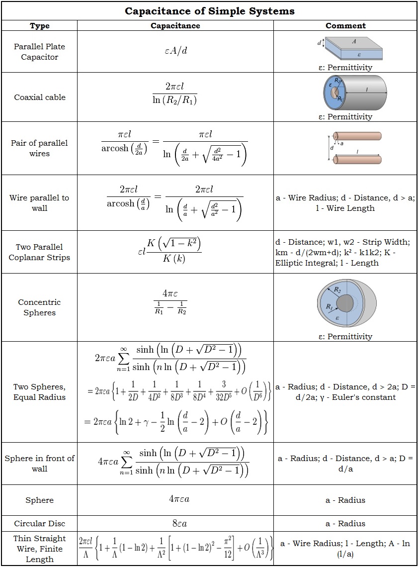
- Capacitance of simple systems
Capacitance
Capacitance of a capacitor is defined as the ability of a capacitor to store the maximum electrical charge (Q) in its body. Here the charge is stored in the form of electrostatic energy. The capacitance is measured in the basicSI units i.e. Farads. These units may be in micro-farads, nano-farads, pico-farads or in farads. The expression for the capacitance is given by,
C = Q/V = εA/d = ε0 εr A/d
In the above equation
C is the capacitance,
Q is the charge,
V is the potential difference between the plates,
A is the area between the plates,
d is the distance between the plates.
ε permittivity of dielectric
ε0 permittivity free space
εr relative permittivity of free space
Self-capacitance
Self-capacitance property is related to the capacitors especially to the isolated conductors. As the name indicates the capacitance is property in an isolated conductor to raise its potential difference to one volt .Generally normal conductors will have mutual capacitance. This is also measured in the S.I units i.e. Farads.
The self-capacitance of a conducting sphere which has the radius ‘R’ is given by,
C=4 πɛoR
Self-capacitance values of some standard devices are given below.
- For the top plate of a van de Graff generator which is having radius of 20 cm self capacitance is 22.24 pF.
- For the planet EARTH self capacitance is 710 uF.
Stray capacitance
Stray capacitance is the unwanted capacitance.The capacitors introduce some capacitance in circuit. But the components like resistors,inductors, even wire will have some capacitance. This is called stray capacitance. Generally at high frequencies this will introduce noise to the circuit. This undesired capacitance is small unless the conductors are close together for long distances or for a large area.
The stray capacitance cannot be eliminated completely but it can be reduced. Circuit designers should take care of stray capacitance while designing the circuit. The separation between the components and the lines should be maintained in order to reduce the unwanted capacitance.
It is also measured in S.I units i.e. Farads.
Examples are capacitance between the turns of the coil, capacitance between two adjacent conductors.
Capacitance of simple systems
Calculation of the capacitance is nothing but solving the Laplace theorem ∇ 2φ = 0 with a constant potential on the surface of a capacitor. The capacitance values and equations for some simple systems are given below.
Charge on a Capacitor
The ability of a capacitor to store maximum charge (Q) on its metal plates is called its capacitance value (C). The polarity of stored charge can beeither negative or positive.Such as positive charge (+ve) on one plate and negative charge (-ve) on another plate of the capacitor. The expressions for charge, capacitance and voltage are given below.
C = Q/V, Q = CV, V = Q/C
Thus charge of a capacitor is directly proportional to its capacitance value and the potential difference between the plates of a capacitor.Charge is measured in coulombs.
One coulomb:
One coulomb of charge on a capacitor can be defined as one farad of capacitance between two conductors which operate with a voltage of one volt.
With Air as its dielectric
The charge ‘Q’ stored in the capacitor having capacitance C, potential difference ‘V’and the air as its dielectric is given by,
Q =C V =(ε× (A ×V)) /d
With a Solid as its dielectric
The charge ‘Q’ of a capacitor having a solid as its dielectric is given by,
Q =C V =(ε0 ×εr× (A ×V)) /d
Here
ε0 is the permittivity of the free space,
εr is the relative permittivity of the dielectric material and
εis the permittivity of the dielectric material.
From the above two cases we can observe
The charge of a capacitor is directly proportional to the area of the plates, permittivity of the dielectric material between the plates and it is inversely proportional to the separation distance between the plates.
Thus larger the area of the plates more is the charge and greater the distance of separation between the plates lesser the charge on the capacitor.
Parallel Plate Capacitor
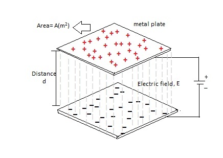
Figure 1.parallel plate capacitor circuit.
The above figure shows the parallel plate capacitor circuit. As we know,thecapacitance is directly proportional to the area of the plates (A) and inversely proportional to the separation distance (d) between two metal plates. The capacitance value of a parallel plate capacitor is given by,
C = k ε0A/d
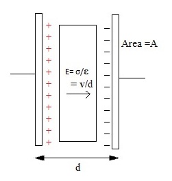
Here k is the dielectric constant, and ε0 is the permittivity of the free space and it is equal to the 8.854 X 10 -12 F/m. The dielectric constant (k) is a parameter related to dielectric material which increases the capacitancecompared to air. Larger surface area of the plates greater is the capacitance value and larger separation distance lower is thecapacitance.One more example for the parallel plate capacitor circuit is show in the below figure.
Figure 2.Parallel plate capacitor.
Capacitance Example No1
Now we will calculate the capacitance of a parallel plate capacitor in pico-farads which is having the surface area of the plates is 200 cm2 and they are separated by the distance of 0.4 cm, and air as its dielectric material.
We know the equation for the capacitance of a parallel plate capacitor is,
C = εA/d
Here ε = 8.854 X 10⁻¹²F/m
A = 200 cm2 = 0.02 m2
D = 0.4 cm = 0.004m
Now we substitute these values in the above equation,
C = 8.854 X 10-12 * (0.02 m2/0.004m) = 44.27 pF
Here the capacitance of a parallel plate capacitor is 44.27 pF
Charging & Discharging of a Capacitor
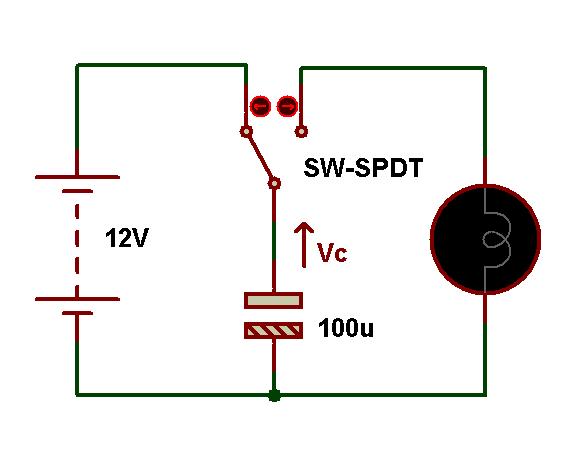
The below circuit is used to explain the charging and discharging characteristics of a capacitor. Let us assume that the capacitor, which is shown in the circuit, is fully discharged. In this circuit the capacitor value is 100uF and the supply voltage applied to this circuit is 12V.
Now the switch which is connected to the capacitor in the circuit is moved to the point A. Then the capacitor starts charging with the charging current (i) and also this capacitor is fully charged. The charging voltage across the capacitor is equal to the supply voltage when the capacitor is fully charged i.e. VS = VC = 12V. When the capacitor is fully charged means that the capacitor maintains the constant voltage charge even if the supply voltage is disconnected from the circuit.
In the case of ideal capacitors the charge remains constant on the capacitor but in the case of general capacitors the fully charged capacitor is slowly discharged because of its leakage current.
Figure: Charging and discharging capacitor circuit
When the switch is moved to the position B, then the capacitor slowly discharges by switching on the lamp which is connected in the circuit. Finally it is fully discharged to zero. The lamp glows brightly initially when the capacitor is fully charged, but the brightness of the lamp decreases as the charge in the capacitor decreases.
Capacitor Charge Example No2
Now let us calculate the charge of a capacitor in the above circuit,we know that, the equation for the charge of a capacitor is
Q = CV
Here, C = 100uF
V = 12V
Now we substitute these values in the above equation,
Q = 100uF * 12V = 1.2mC
Hence the charge of capacitor in the above circuit is 1.2mC.
Current through a Capacitor
The current (i) flowing through any electrical circuit is the rate of charge (Q) flowing through it with respect to time. But the charge of a capacitor is directly proportional to the voltage applied through it. The relation between the charge, current and voltage of a capacitor is given in the below equation.
I (t) = d Q(t)/dt = C dV(t)/dt
We know that
Q = CV
V = Q/C
V (t) = Q(t)/C
Q(t) =C V(t)
The current to voltage relation is given by, I (t) = C dV(t)/dt
From this relation we observed that the current flowing through the capacitor in the circuit is the product of the capacitance and the rate of change of voltage applied to the circuit. The current flowing through the capacitor is directly proportional to the capacitance of a capacitor and the rate of voltage.
Larger the current, higher is the capacitance of the circuit and higher the applied voltage,larger the current flowing through the circuit. If voltage is constant then charge is also constant.Thus there is no flow of charge. Hence the current flowing through the circuit will become zero.
Unit of capacitance (Farad)
Josiah Latimer Clark in the year of 1861first used the termFarad. Farad is a standard unit of the capacitance. This is an extremely a large unit for the capacitance.
One farad of capacitance is defined as the capacitance with one coulomb of charge which operates at the voltage of one volt.
C = Q/V
1Farad = 1Coluomb/1Volt
Now capacitors are available with large capacitance values of hundreds of farads. These capacitors with high capacitance values are called as “super capacitors”. These capacitors are utilizing large surface area to deliver high energy because these have high capacitance values.
At low voltage, super capacitors have the ability to store high energy with high capacitance values. These high energy super capacitors are used in hand held portable devices to replace large, heavy and expensive lithium type capacitors, because they store high energy, like batteries. These capacitors are also used in audio and video systems in vehicles by replacing the high batteries.
Sub-units of the Farad
The standard unit of capacitance is farad. But this is generally a large unit for the measurement of capacitance. This farad has some sub units; they are micro-farads (uF), nano-farads (nF) and pico-farads (pF).
The relation between these all sub-units with farad are
1micro-Farad (uF) = (1/1000000) F = 10-6 F
1nano-Farad (uF) = (1/1000000000) F = 10-9 F
1pico-Farad (uF) = (1/1000000000000) F = 10-12 F
Now we will see the some conversions between the sub-units of capacitance,
(i) conversion of 33pF to nF => 33pF = 0.033nF
(ii) conversion of 22nF to uF => 22nF = 0.022uF
(iii) conversion of 11uF to F => 11uF = 0.11F
Energy in a Capacitor
Energy is the amount of some work against the electro-static field to charge the capacitor fully. In the capacitor at initial stage of charging, the charge Q transferred between the plates from one plate to another plate. This charge either +Q or –Q is interchanged between two plates of a capacitor. After transformation of some charge an electric field is formed between the plates, in that case we need some extra work to charge the capacitor fully. This extra work is called as the energy stored in a capacitor. The energy is measured in the units of Joules (J). Now we see the equations for this energy and work.
dW = V dQ
dW = (Q/C) dQ
After integration of the above equation is,
W = Q2/2C
W = (CV)2/2C
W= CV2/2 Joules
Finally we get the energy stored in a capacitor is
Energy (W) = CV2/2 Joules
Now we calculate the energy stored in a capacitor of capacitance 200 uF which operate with voltage of 12V.
W = CV2/2
W = (200×10-6×122)/2 = 14.4 m J


3 Responses
Thank you a thousand times for making this tutorial available. I am very fond of electronics but I lack the wherewithal to embark on course.
Is the area in meters for the equation C=KE0A/D and same with the distance between the plates
What are the units in for the equation C=KE0A/D?