Whenever two conducting plates are separated by a dielectric or insulating medium, a capacitor is formed. The fundamental property of a capacitor is to store the electric charge. If a voltage source is connected across a capacitor, the two plates gain opposite electric charge that means one plate accumulates positive charge, the other accumulates negative charge.
This causes to flow the electrons from one plate to the other until the voltage across the capacitor is equal to the applied voltage. The rate of change of voltage across the capacitor decides the flow of current through the capacitor.
Capacitors along with resistors and inductors help to build very complex AC circuits in many electronic applications. Let us discuss the behavior of AC circuit with capacitance in brief.
What Are AC Capacitive Circuits?
AC (alternating current) capacitive circuits are electrical circuits that contain capacitive elements and operate with alternating current. Capacitors are passive electronic components that store and release electrical energy in the form of an electric field between two conducting plates separated by an insulating material, called a dielectric.
AC Applied Across a Pure Capacitor
When a pure capacitor is connected to AC source, a changing value of the applied voltage causes the capacitor to charge and discharge alternatively. The charge that flows through the capacitor is proportional to the capacitance (size of the capacitor) and the applied voltage across the capacitor. It can be expressed as
Q = C V
V= Q / C
Where
V = Applied voltage in volts
Q = charge on the capacitor in coulombs
C = capacitance of the capacitor in farad
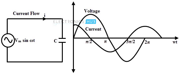
Consider the above circuit in which a pure capacitor is connected across an AC voltage source of v = Vm sin ωt. The voltage source results the flow of current through the circuit. The current is proportional to the rate of change of charge on the capacitor with respect to time.
Current in the circuit, i = d(q)/dt
Substituting q = C v = C Vm sin ωt on above equation, we get
i = d/dt (C Vm sin ωt) = ωC Vm cos ωt
or i = ω C Vm sin (ωt + π/2)
When the term sin (ωt + π/2) is unity, the value of current will be at maximum, i.e.,
im = ωC Vm
Substituting this current value, we get
i = im sin (ωt + π/2)
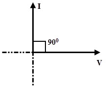
From the above equations, it is clear that in a pure capacitive circuit, current leads the voltage by 900. This means that when a pure capacitor is connected across the AC supply, the maximum current flows through the capacitor when the rate of change of voltage is at maximum (at zero voltage position). And this current diminishes when the rate of change of voltage is at minimum.
In other way, because of the discharged state of the capacitor, the current through the circuit is at maximum when the voltage starts increasing across the capacitor.
As the capacitor charges fully to the maximum value of the voltage, the charging current drops towards zero. When the voltage begins to drop, capacitor starts charging. So the relation between the voltage and current is described as 90 degrees out of phase.
Therefore, the capacitor current leads the applied voltage by an angle 90 degrees. The phasor diagram for AC capacitive circuit is given below.
Capacitive Reactance
From the above derivation, the maximum current equation is given as
im = ωC Vm
Vm / im = (1 / wC)
This ratio of voltage to current is the opposition offered by the capacitive circuit to the current flow. This (1 / w C) quantity is termed as capacitive reactance and it is denoted as XC, measured in Ohms.
The capacitive reactance of the AC circuit can be represented as
XC = (1 / ω C) = (1 / 2πf C) (since ω = 2Πf)
Where
XC is the capacitive reactance in Ohm’s
f is the frequency of the supply voltage
C is the capacitance of a capacitor in farads
From the above equation, capacitive reactance of a capacitor in an AC circuit is the function of frequency and capacitance. The capacitive reactance decreases with increasing frequency which results more current to flow through the circuit.
Similarly, decreasing frequency increases the reactance that results the decrease of current flow. The relation between capacitive reactance and frequency is given in the below figure.

Power and Power Factor in Capacitive AC Circuit
The power in an AC circuit is the product of instantaneous voltage and current. This can be given as
P = v × i
P = Vm sin ωt × Im sin (ωt + 90)
Taking integration over a cycle we get,
P = Vm sin ωt × Im sin (ωt + 90)
P = 1/2π (∫02π Vm sin ωt × Im sin (ωt + 90) dwt)
= (Vm Im / 2π) (∫02π sin ωt cos ωt dwt)
= (Vm Im / 4π) (∫02π ( sin 2 ωt)/2 dwt)
= (Vm Im/ 8π) (– cos 4π + cos 0)
= (Vm Im / 8π) (– 1 + 1)
P = 0
Thus, similar to inductive circuit, power absorbed in pure capacitance is zero as the power absorbed and returned back during each half cycle. The figure below shows the voltage, current and power waveforms of an AC capacitive circuit.
During the positive half cycle of the power waveform, the energy is stored in the capacitor while it is charging. And during the negative half cycle, energy stored is returned back to the source while it is discharging. It is to be observed that the areas of both cycles are equal and hence the average power absorbed by the circuit is zero.

In this pure capacitive circuit, there is a phase difference of 900 (leading) between voltage and current waveforms. Then the power factor becomes
The power factor, cos θ = cos 900 = 0
Hence the power factor in a pure capacitive circuit is zero leading, i.e., pure leading power factor.
RC Series Circuit
This type of circuit is similar to the RL series circuit but in place of inductor, capacitor is employed. In the below figure, series arrangement of resistance and capacitor is connected across the AC source.
The voltage drop across the resistance is in phase with the current while current leads the voltage drop across the capacitor by 900 as shown in the below figure.
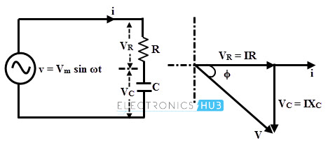
Voltage drop across the resistor, VR = IR
Voltage across pure capacitor, VC = I ×XC (where XC = 1/ 2πfC)
Thus V = √ (VR2 + VC2) = √ (IR)2 + (I XC)2)
= I √ (R 2 + XC 2) = IZ
Where Z is the impedance in RC series circuit and is equal to √ (R 2 + XC2).
Impedance Triangle
From the RC series phasor diagram,
tan ϕ = VC/ VC = XC / R
cos ϕ = VC/ V = R / Z
sin ϕ = VC / V = XC / Z
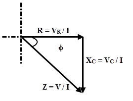
From the impedance triangle, R, XC and total impedance in RC series circuit can be expressed as
R = Z cos ϕ
XC= Z sin ϕ
Z = √ (R 2 + XC2)
And ϕ = tan-1 (-XC / R)
RLC Series Circuit
In this circuit a series connection of resistor, inductor and capacitor is connected across the AC supply source. Depends on the resultant value from the combinations of capacitive and inductive reactances, the circuit will be operated either RL or RC circuit. By subtracting the larger reactance from the smaller reactance, total reactance is obtained.
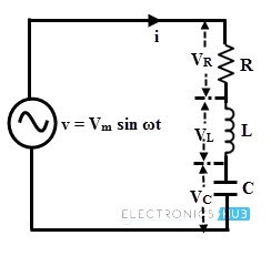
Voltage across the resistor, VR = IR
Voltage across the inductor, VL = I XL
Voltage across pure capacitor, VC= I XC
The phasor diagram of this circuit depends on the values of XL and XC, let us consider different values of these reactances.
(1) XL > XC
If XL > XC, then VL (= I XL) is greater than VC (= I XC). Therefore the circuit is inductive in nature as the resultant of VLand VC is directed towards VL. Thus circuit behaves like an RL series circuit.
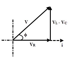
Thus the supply voltage, V = √ ((VR2 + (VL – VC)2) = √ ((IR)2 + (I XL– I XC)2)
V = I √ ((R)2 + (XL– XC) 2)
V = IZ
Where Z = √ ((R)2 + (XL– XC)2)
(2) XL < XC
If XL < XC or XC >XL then VL (= I XL) is less than VC (= I XC). Therefore the circuit is capacitive in nature as the resultant of VL and VC is directed towards VC. Thus the circuit behaves like an RC series circuit.
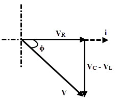
Thus the supply voltage, V = √ ((V2R + (VC – VL)2) = √ ((IR)2+ (I XC– I XL)2)
V = I √ ((R)2 + (XC– XL)2)
V = IZ
Where Z = √ ((R)2 + (XL– XC)2)
(3) XL = XC
If XL = XC, then VL= VC. In such case the resultant voltage is zero. Therefore, VR = V. Hence the circuit behaves as resistive circuit.
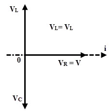
Form the phasor diagram,
V = VR
V = I R
V = I Z
Where Z = R.
Example
A single phase AC sinusoidal voltage of v = 283 sin 314t is connected across a pure capacitor of 100 µF. Then find the current flowing through the capacitor.
Converting the voltage from time domain to polar form, we get
v = 283 sin 314t = 283∠00
The capacitive reactance can be determined as
XC = (1 /j w C) = (1 / 314 × 100µ) = 31.8 ∠– 900
According to the Ohm’s law, the current flowing through the circuit can be obtained as
Ic = (V /j X<subC)
Ic = (283∠00 /31.8 ∠– 900)
Ic = 8.8 ∠+900)

One Response
I am happy to be part of this great forum