In this project, I will show you how a Bipolar LED Driver Circuit can be implemented using 8051 Microcontroller. A Bipolar LED is different from a regular Bi-color LED in the sense that a Bipolar LED has only two leads whereas a regular Bi-color LED has three leads.
Introduction
A Bi color LED is a special type of LED which consists of two diodes connected in inverse direction to each other inside a package. A bi color LED generally consists of three terminals – a common pin and two separate pins. The common pin can be connected to ground if it is a common cathode LED or connected to +5V supply, if it is a common anode. However, there is another type of bi color LED with two terminals called the Bipolar LED.
The device functions as per the positive signal given to one of the terminals. For instance for a green and red bi color LED, a positive signal at the green terminal and negative signal at red terminal ensures the green LED to be forward biased and red LED to be reverse biased. This causes the green light to flash. Same is the case for the red LED.
However, if both the terminals are given negative signals, neither of the diodes would conduct and the device would remain off. If positive signal is applied to both the terminals, a different color, based on the combination of the LED colors, would flash.
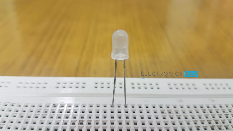
The following is the image of a red – green Bipolar LED. It looks like a regular LED.
Related Post: Bi Color LED Dancing Lights
In this project, we are designing a simple bi color LED driver circuit using an 8051 Microcontroller. The LED used here has a forward voltage drop of 2.2V and hence can be biased using a 5V supply. The control is done by the microcontroller program, based on the inputs given from two push buttons.
Principle behind Bipolar LED Driver Circuit
The circuit uses a microcontroller to drive the bipolar LED. The input command is given from the two push buttons and based on the inputs; the microcontroller is configured to send appropriate HIGH or LOW signals to the two output pins. These output pins are connected to the terminals of the bi-polar LED.
Bipolar LED Driver Circuit Diagram
Components Required
- 8051 Microcontroller (AT89C51 is used here)
- Programmer for 8051 Microcontroller
- 11.0592 MHz Crystal
- Capacitors – 2 X 33pF, 10µF
- Resistors – 150Ω, 10KΩ X 2
- Push Buttons X 3
- Bipolar LED (two leads)
- Connecting Wires
- Breadboard
- Power Supply
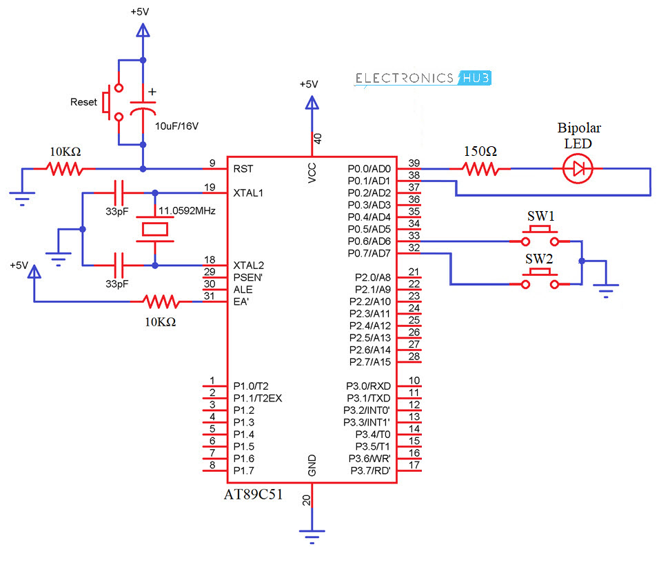
Bipolar LED Driver Circuit Design
It is a simple circuit and the design mainly involves designing the interfacing of Microcontroller, designing the oscillator and reset circuits for the microcontroller and selection of the LED resistor.
The microcontroller interfacing is accomplished by connecting two push button switches to port P0 Pins P0.6 and P0.7 and connecting the two terminals of bipolar LED to port P0 Pins P0.0 and P0.1.
The oscillator design is done by selecting two 33pF ceramic capacitors in order to provide stability. The clock signal is generated using an 11MHz Crystal Oscillator. The reset circuit is designed by selecting an electrolyte capacitor of 10uF and a resistor of 10K to achieve a reset pulse width of 100ms. The voltage drop across the resistor is kept around 1.2V.
Software Part of the Project
The software part of design involves writing the code for the microcontroller and generating the .hex file. This involves the following steps.
- Create a new project in the Keil µVision IDE window.
- Select the target device for the project. Here, we are using AT89C51 from Atmel (now Microchip).
- Create a new file such that a blank text field appears.
- Write the code using the following algorithm.
- Assign variables to the input and output port.
- Check if one of the inputs is active low.
- In case one of the inputs is at logic low, assign a logic high signal to one of the LED terminals.
- In case none are at logic low, make sure the LED is switched off.
- Save the code with .c extension.
- Add the code to the source folder under target folder.
- Create a Hex file by clicking the ‘Configure Flash Tools’ under ‘Flash’ menu.
Also Read the Related Post: 230v LED Driver Circuit
Code
Working of Bipolar LED Driver Circuit
Once the circuit is switched on, the microcontroller continuously scans the input pins at port P0. Suppose the first button (P0.6) is pressed, the microcontroller receives a low logic signal at the corresponding input pin and accordingly it assigns a high logic signal to pin P0.0 and low logic signal to pin P0.1. This causes the red light of the LED to glow.
Now when the second button is pressed, the microcontroller will accordingly assign a low logic signal to the pin P0.0 and a high logic signal to pin P0.1. This causes the green light to glow.
The LED stays on until the button is released.
Bipolar LED Driver Applications
- This circuit can be used for indication purposes.
- This circuit can be used at applications where flashing of light is required, as in beacon flashing.
Limitations of Bipolar LED Driver Circuit
- The main limitation of the project is not in terms of the functionality but rather the availability of the Bipolar LEDs.

5 Responses
very good
hi sir
Nice and quite clear
its very clear and clarity thank you for your information
very good thank you