Stepper Motor Control using Arduino is a simple project where a Bipolar Stepper Motor is controlled using Arduino UNO. Stepper Motor is a type of brushless DC Motor that converts electrical pulses into distinct mechanical movements i.e. the shaft of a stepper motor rotates in discrete steps. When a computer controls these steps, we can get precise position and speed control.
Because of this discrete nature of step – wise rotation of a stepper motor, they are often employed in industrial automation, CNC systems, etc. where precision motion is required.
In this project, we designed a simple system to control a stepper motor using Arduino. We have used Arduino UNO as the main controlling part of the project to control the steps of the stepper motor.
In the following sections, a brief introduction to stepper motors, circuit of the project and also the working of the project is explained.
Circuit Diagram of Stepper Motor Control using Arduino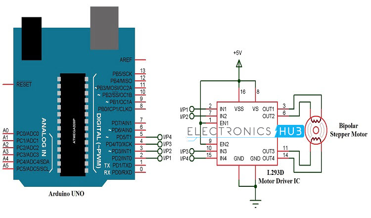 Components Required
- Arduino UNO [Buy Here]
- L293D Motor Driver IC [Buy Here]
- Bipolar Stepper Motor
- Power Supply (suitable for your stepper motor)
- Breadboard (Prototyping Board)
- Connecting Wires
A brief introduction to Stepper Motor
As mentioned earlier, a Stepper Motor is a type of DC Motor that rotates in discrete steps. Due to their unique design, stepper motors can be controlled for precise positioning without any feedback.
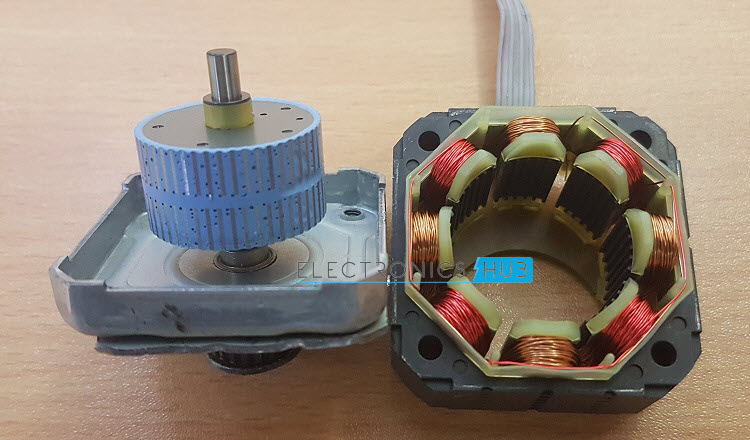
A typical stepper motor has multiple coils that are divided into phases. When each phase is energised in sequence, the rotor of the stepper motor rotates in steps.
Basically, there are three types of stepper motors: Variable Reluctance (VR) Stepper Motors, Permanent Magnet (PM) Stepper Motors and Hybrid Stepper Motors. Based on the winding of the stator, stepper motors can also be classified as Bipolar Stepper Motors and Unipolar Stepper Motors.
We will not go into the details of the types of stepper motors but it is important to identify whether your stepper motor is a bipolar or unipolar one. This is because, the driving method for each of these stepper motors is different from the other.
For instance, the driver circuit of a unipolar stepper motor can be implemented with simple transistor based circuit or a Darlington Transistor IC like ULN2003A. But in case of a bipolar stepper motor, we need to implement an H – bridge type driver like L293D Motor Driver IC.
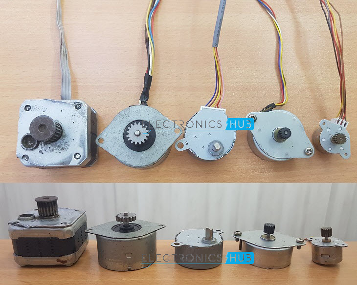
The following image shows a bipolar stepper motor, a 6 – wire unipolar stepper motor and a 5 – wire unipolar stepper motor.
The most common step angle or step count for stepper motors is 1.80 or 200 steps (both of them are same as 1.80 x 200 = 3600).
How to Design Stepper Motor Control Circuit?
In this project, we have used a bipolar stepper motor. Hence, we used the Motor Driver IC L293D, which is an H – bridge type driver. Since it is a bipolar stepper motor, there are only 4 wires we need to connect.
So, connect the two wires from one coil to outputs 1 and 2 of L293D and the other two wires from second coil to outputs 3 and 4.
The 4 inputs of the L293D Motor Diver IC are given from Arduino UNO. So connect them to any of the 4 digital I/O pins (here, we connected them to pins 2, 3, 4 and 5 of Arduino UNO).
Understand the power requirements of your stepper motor and provide necessary power supply. Wrong power supply would permanently damage the motor.
The control of steps is done with the help of computer using serial monitor. So, make sure that the RX and TX pins of the Arduino are not used as digital I/O. Alternatively, we can control the steps or rotation of the motor with the help of analog input via a potentiometer.
Working of the Project
A simple Stepper Motor Control using Arduino UNO and L293D Motor Driver IC is designed in this project. The working of the project is explained here.
The stepper motor used in this project is a Bipolar PMH (Permanent Magnet Hybrid) type Stepper Motor. Since it is a bipolar motor, there are only 4 wires corresponding to the end terminals of two coils. These 4 wires are connected to the output pins of the L293D Motor Driver IC.
In order to drive the stepper motor, we will be using a technique called “Half Stepping”. The motor used in this project has 200 step count. With one phase stepper excitation i.e. energising only one phase at a time, we can achieve the normal 200 step rotation with least power consumption.
Two phase stepper excitation is another technique where two phases are energised at a time. With this technique, the step count doesn’t vary from the one phase excitation but the torque and speed is significantly increased.
But the disadvantage is it requires twice the power. The following image shows a 4 step based operation of one phase and two phase excitation methods.
 There is another technique called Half Stepping. This is a combination of one phase and two phase excitation. The step count is doubled i.e. half the step angle can be achieved.
So, with half stepping, we can get double the resolution with along with smoother operation. The image below demonstrates an 8 step “Half Stepping” excitation method.

As mentioned earlier, the step angle of the motor used in this project is 1.80 i.e. 200 steps for full step excitation. In order to increase the resolution (double the resolution), we will use half step excitation and achieve 400 step count.
In order to control the steps, we will use the serial monitor. In the program, for clock wise rotation, ‘+’ symbol is assigned and for anti – clock wise rotation, ‘–’ sign is used.
After selecting the direction, then we can enter the number of steps directly anywhere between 1 and 400.
Code
Applications
- The project demonstrates the working of a Stepper motor and Stepper Motor Control using Arduino. Stepper motors are commonly used in robots, CNC Machines, industrial automation, small appliances like printers etc.
- Due to their high accuracy and holding torque, stepper motors are used where precision positioning is essential.
Construction and Output Video

7 Responses
please send me rating stepper motor which is used in this project????
Hi, We have used a 5V Bipolar Stepper Motor.
what is the cost of the motor used
There are a variety of Stepper Motors you can buy. The price may be in the range of Rs. 100 to Rs. 500.
i want to make a project of automatic car wiper control circuit but i have stuck between a stepper motor and serve motor .which one is more suitable for using in this project?
Which type of program this
Like c++ ,java, empaded??
I want to use a stepper motor to rotate a piece of art I am planning. Th weight to be rotated will be about 10-15 pounds. The end result expected is:
Step 1: Rotate smoothly 120 degrees (duration of rotation 15 seconds)
Step 2: Hold position for 30 seconds
Repeat Steps 1 & 2 continually until switched off.
What type of stepper motor do you recommend?