In this tutorial, I will show you the procedure for Interfacing Stepper Motor with STM32F103C8T6 MCU based STM32 Blue Pill Board. I will first give a brief overview of the Stepper Motor, its types, its driving techniques and finally how to interface a Stepper Motor with STM32.
Introduction
Stepper Motors are one of the important types of motors used in industrial as well as commercial applications. They are simple brushless motors that convert digital pulses into angular rotation.
The unique feature of a Stepper Motor is that every revolution is divided into a distinct number of equal steps, usually 200. Since there are 200 steps for 3600 of rotation, each step will result in a rotation of 1.80. In order to, move from one step to other, a separate pulse must be sent and speed of rotation is directly proportional to the frequency of the pulses.
Another important thing to know about stepper motors is there are two types of Stepper Motors. They are Unipolar Stepper Motors and Bipolar Stepper Motors. The main difference between these two is that in unipolar stepper motor, each phase has a winding with centre tap while in bipolar stepper motor, there is just a single winding per phase.
Another difference is the way these motors are driven. Since the polarity of the magnet in the coil can be reversed in Unipolar type, without the switching the current direction, driving them is very easy. You only need a simple transistor-based motor driver like ULN2003 IC, for example.
But in case of Bipolar stepper motors, it is difficult to reverse the magnetic polarity directly as there is only a single winding per phase. We usually need a dedicated H-Bridge type Motor Driver IC like L293D or L298N IC to drive a bipolar stepper motor.
Interfacing Stepper Motor with STM32F103C8T6
In this project, I will be using a simple 5V Unipolar Stepper Motor, where the centre taps of both the windings are made common. This means that the motor will have only 5 wires instead of six.
A common type of hobbyist unipolar stepper motor that is very popular and cheap is the 28BYJ-48. If you refer to the data sheet of this motor, it is mentioned that it has a gear ratio of 64 and the stride angle is 5.6250. What this means is that the number if steps needed for one rotation is 360 / 5.625, which is equal to 64.
Also, since the gear ratio is 64, the effective number of steps for the output shaft is steps per revolution multiplied by the gear ratio i.e. 64 * 64 = 4096.
In this project, I will be using this stepper motor along with ULN2003 Driver IC and control it with STM32 MCU. The project will be a sweep of rotation in clockwise direction and anti-clockwise direction in a loop.
Components Required
- STM32F103C8T6 MCU based STM32 Blue Pill Board
- 5V Unipolar Stepper Motor (5 Wire)
- ULN2003 Driver IC
- Connecting Wires
- USB to UART Converter (if programming through UART)
Circuit Diagram
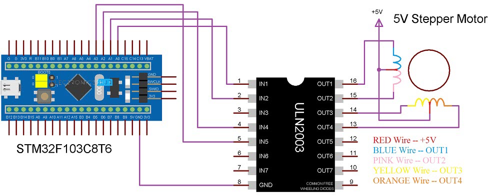
The following image shows the circuit diagram of Interfacing Stepper Motor with STM32F103C8T6 MCU.
Connections Explained
First, the red wire of the Stepper Motor is connected to 5V. Next, the first four inputs IN1 through IN4 of ULN2003 IC are connected to PA0 through PA3. The first four outputs of ULN2003 i.e. OUT1 through OUT4 are connected to the Stepper Motor Wires in the following order:
- OUT1 –> Blue
- OUT2 –> Pink
- OUT3 –> Yellow
- OUT4 –> Orange
Also, connect the GND terminals of ULN2003, STM32 and the 5V power supply.
Programming STM32 for Stepper Motor Control
First, select the pins PA0 through PA3 as inputs to ULN2003 and initialize them as Outputs of STM32.
Now use a variable to denote the maximum number of steps as 4095. What this represents is the count for one full rotation. Now assume the initial direction as clockwise and start the stepper motor by using half stepping technique.
Once the step count reaches 0, it means that the motor has completed one rotation. Now, give a small delay of a second or two and change the direction to anti-clockwise. Reset the step count to maximum i.e. 4095 and begin the sequence in reverse order. The stepper motor will start rotating in the opposite direction. Repeat this process in a loop.
There is no need for any library in this code and you can even modify the code to accept user inputs for selecting the direction and the number of steps.
If you have a different stepper motor, then refer to its data sheet and calculate the step angle, gear ratio and total number of steps required for one rotation.
Code
#define IN1 PA0
#define IN2 PA1
#define IN3 PA2
#define IN4 PA3
int Steps = 0;
boolean Direction = true;
unsigned long prevTime;
unsigned long currentMillis ;
int stepsLeft=4095;
long time;
void setup()
{
pinMode(IN1, OUTPUT);
pinMode(IN2, OUTPUT);
pinMode(IN3, OUTPUT);
pinMode(IN4, OUTPUT);
}
void loop()
{
while(stepsLeft > 0)
{
currentMillis = micros();
if(currentMillis-prevTime >= 1000)
{
stepper(1);
time = time + micros() – prevTime;
prevTime = micros();
stepsLeft–;
}
}
delay(2000);
Direction=!Direction;
stepsLeft=4095;
}
void stepper(int x)
{
for (int i=0; i < x; i++)
{
switch(Steps)
{
case 0:
digitalWrite(IN1, LOW);
digitalWrite(IN2, LOW);
digitalWrite(IN3, LOW);
digitalWrite(IN4, HIGH);
break;
case 1:
digitalWrite(IN1, LOW);
digitalWrite(IN2, LOW);
digitalWrite(IN3, HIGH);
digitalWrite(IN4, HIGH);
break;
case 2:
digitalWrite(IN1, LOW);
digitalWrite(IN2, LOW);
digitalWrite(IN3, HIGH);
digitalWrite(IN4, LOW);
break;
case 3:
digitalWrite(IN1, LOW);
digitalWrite(IN2, HIGH);
digitalWrite(IN3, HIGH);
digitalWrite(IN4, LOW);
break;
case 4:
digitalWrite(IN1, LOW);
digitalWrite(IN2, HIGH);
digitalWrite(IN3, LOW);
digitalWrite(IN4, LOW);
break;
case 5:
digitalWrite(IN1, HIGH);
digitalWrite(IN2, HIGH);
digitalWrite(IN3, LOW);
digitalWrite(IN4, LOW);
break;
case 6:
digitalWrite(IN1, HIGH);
digitalWrite(IN2, LOW);
digitalWrite(IN3, LOW);
digitalWrite(IN4, LOW);
break;
case 7:
digitalWrite(IN1, HIGH);
digitalWrite(IN2, LOW);
digitalWrite(IN3, LOW);
digitalWrite(IN4, HIGH);
break;
default:
digitalWrite(IN1, LOW);
digitalWrite(IN2, LOW);
digitalWrite(IN3, LOW);
digitalWrite(IN4, LOW);
break;
}
SetDirection();
}
}
void SetDirection()
{
if(Direction==1)
{
Steps++;
}
if(Direction==0)
{
Steps–;
}
if(Steps>7)
{
Steps=0;
}
if(Steps<0)
{
Steps=7;
}
}
Conclusion
A simple project is implemented here to demonstrate the Interfacing of Stepper Motor with STM32F103C8T6 MCU based STM32 Blue Pill Board.

One Response
Thanks for the code, I’m working on it.