Basically, Decoder is a combinational logic circuit that converts coded input to coded outputs provided both of these are different from one another. The name decoder means translating of coded information from one format into another. So the input code generally has fewer bits than output code word.
A digital decoder converts a set of digital signals into corresponding decimal code. A decoder is also a most commonly used circuit in prior to the use of encoder. The encoded data is decoded for user interface in most of the output devices like monitors, calculator displays, printers, etc. once after the information is encoded by encoders. In this article we are going to study on different types of binary decoders.
Binary Decoders
A binary decoder is a multi-input, multi-output combinational circuit that converts a binary code of n input lines into a one out of 2n output code. These are used when there is need to activate exactly one of 2n output based on an n-bit input value.
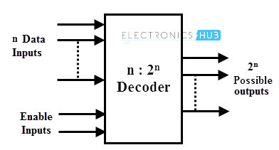
The figure below shows the general structure of binary decoder in which encoded information is accepted at n input lines and the output is produced at 2n possible output lines.
Generally, decoders are provided with enable inputs so as to activate the decoded output based on data inputs. As an example, in case of BCD code, the 4 bit combinations from 0000 through 1001 are enough to represent the decimal digits 0 to 9.
Depending on the number of input lines, the inputs of a binary code can be 2-bit or 3-bit or 4-bit codes. Upon the availability of 2n lines, it activates the one of its output by deactivating (making logic 0) all other input whenever it receives n inputs.
Usually the number of bits in output code is more than the bits in its input code. The most commonly used practical binary decoders are 2-to-4 decoder, 3-to-8 decoder and 4-to-16 line binary decoder.
2-to-4 Binary Decoder
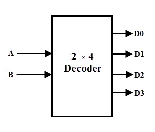
In a 2-to-4 binary decoder, two inputs are decoded into four outputs hence it consists of two input lines and 4 output lines. Only one output is active at any time while the other outputs are maintained at logic 0 and the output which is held active or high is determined the two binary inputs A and B.
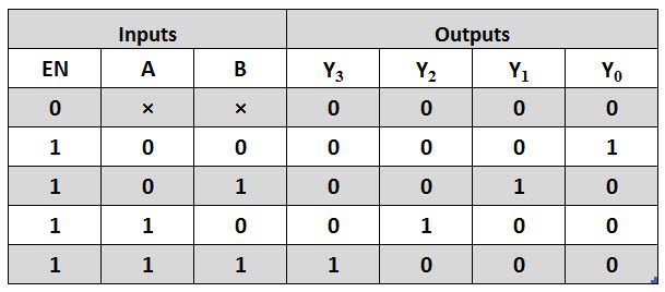
The figure below shows the truth table for a 2-to-4 decoder. For a given input, the outputs Y0 through Y3 are active high if enable input EN is active high (EN = 1). When both inputs A and B are low (or A= B= 0), the output Y0 will be active or High and all other outputs will be low.
When A = 0 and B = 1, the output Y1 will be active and when A = 1 and B = 0, then the output Y2 will be active. When both the inputs are high, then the output Y3 will be high. If the enable bit is zero then all the outputs will be set to zero. This relationship between the inputs and outputs are illustrated in below truth table clearly.
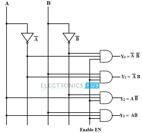
From the above truth table we can obtain Boolean expression for the each output as
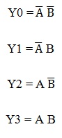
These expressions can be implemented by using basic logic gates. Thus, the logic circuit design of the 2-to-4 line decoder is given below which is implemented by using NOT and AND gates. Two NOT gates or inverters provide the complement of inputs.
A common enable line is connected to each AND gate such that when EN= 0 all the outputs are zero and if EN=1, depends on the inputs A and B, outputs are produced. Each output represents one of the minterms of the 2 input variables.
It is also possible to design 2-to-4 decoder using NAND gates as shown in figure below along with truth table. This is constructed with a principle of max terms as outputs. To generate the minterms, we have to use NAND gates which act as inverters. If both inputs are zero (A = B = 0), Y0 will be zero , if A = 0 and B= 1, then Y1 will be 1 and so on.
Therefore, only one output will be low for any combinations of inputs at a given time and all other outputs will be high. This type of decoders is available in IC forms so that 3 to 8, 4 to 16, and 5 to 32 decoders can also be made depends on the application requirement.
3-to-8 Decoder
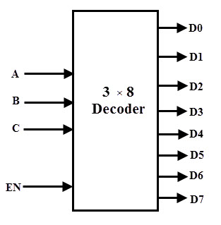
In a 3-to-8 decoder, three inputs are decoded into eight outputs. It has three inputs as A, B, and C and eight output from Y0 through Y7. Based on the combinations of the three inputs, only one of the eight outputs is selected.
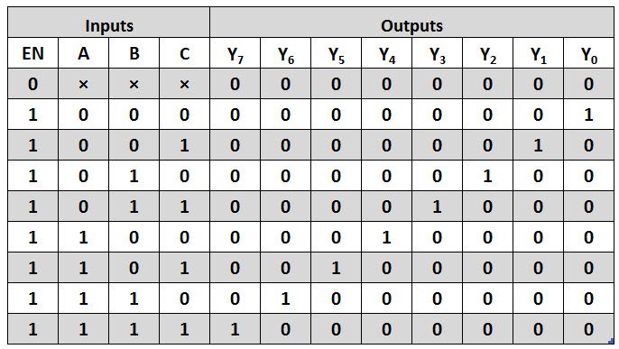
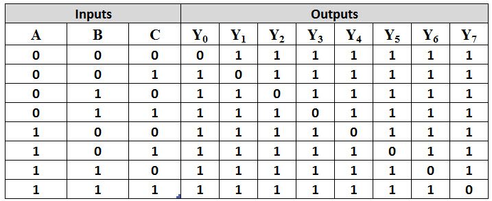
The figure below shows the truth table of a 3-to-8 decoder. Enable input is provided to activate the decoded output depends on the input combinations A, B and C. Suppose if A = B=1 and C= 0, then the output Y6 is 1 and all other outputs are zero. So from the truth table, minterms represents the each output equation and are given as
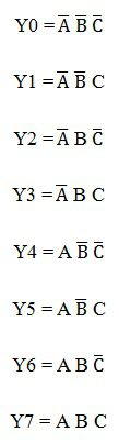
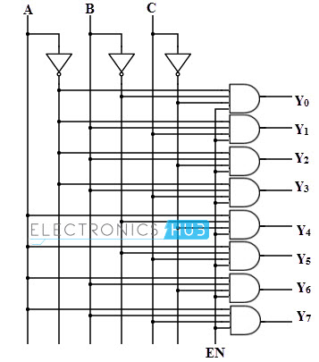
Using the above min term expressions for each output, the circuit of 3-to-8 decoder is can be implemented by using three NOT gates and eight AND gates. Each NOT gate provides the complement of the input and AND gates generates one of the minterms.
Also enable input activate the decoded output depends on the input data. The logic diagram of this decoder is shown below.
Only one of eight outputs is high at a given time for a particular input combination, that why this decoder is also called as 1-of-8 decoder. Suppose, when ABC = 011, then only AND gate 4 has all inputs high, thus Y3 is high.
Also, 3-bit binary numbers at the input is converted to eight digits at the output (which is equivalent to octal number system), that’s how; it is also called as a binary-to-octal decoder
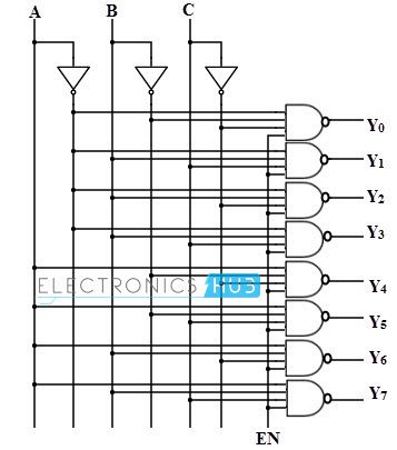
It is also possible represent the each output equation using max terms. In such case, inversion operation is performed in the logic circuit than that of circuit with min terms. The figure below shows the truth table of 3-to-8 line decoder using NAND gates. Each output in the table gives a max term representation.
At a given time only one output is low and all other outputs will be high. For example, when A=B= 1 and C=0, then the output Y6 is zero and all other outputs are high as shown in below figure.
From the above table , a 3-to-8 line decoder is designed by using three NAND gates and three NOT gates. NOT gates generate the complement of input while the NAND gates generate max terms of each output as shown in below figure.
4-to-16 Decoder
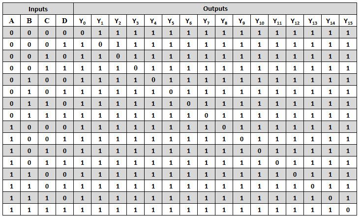
A 4-to-16 decoder consists of 4 inputs and 16 outputs. Similar to all the decoders discussed above, in this also only one output will be low at a given time and all other outputs are high (using maxterms).
The truth table of this type of decoder is shown below. If the input to this decoder is 1000, then output Y8 will be low and all other outputs will be high as shown in figure. This will be so on for all the input combinations.
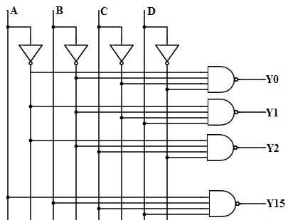
From the above truth table, a 4-to-16 decoder can be implemented by using 4 NOT gates and 16 decoding NAND gates. For decoding all possible combinations of 4 bits input, sixteen (24 = 16) decoding gates are required.
It is important to note that all the NAND gates are implemented on this circuit produce the active low outputs as shown in figure.
Since it selects one of 16 outputs based in the particular input combination, these decoders are also called as 1-of-16 decoder. And also its output represents the sixteen digits as hexadecimal number system, this type of decoder is also called as a binary-to-hexadecimal decoder.
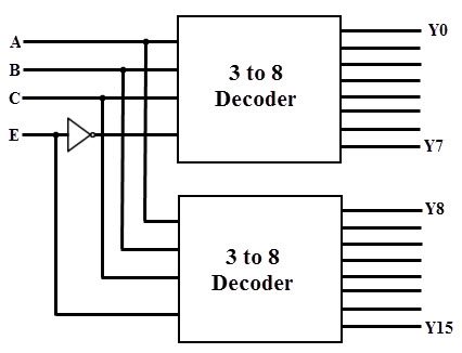
It is possible to combine or cascade two or more decoders to produce a decoder with larger number of input bits with the use of enable input of decoder. The cascade combination of two 3-to-8 line decoder is given below figure. It consists of four inputs A, B, C and Enable E and 16 outputs Y0 to Y7.
One of the input variable is used as enable input of the first 3-to-4 decoder and this same input is complemented and connected as enable input of the second decoder. The decoder to be enabled is decided by the most significant input variable and other input variables are fed to each decoder.
When enable input is zero then the top decoder is enabled while the other is disabled. Then the top decoder eight outputs generate the minterms 0000 to 0111. Likewise, when enable is 1, the lower decoder is enabled and top one is disabled. Thus the bottom decoder outputs generate minterms from 1000 to 1111.
Applications of Decoders
Decoders are greatly used in applications where the particular output or group of outputs to be activated only on the occurrence of a specific combination of input levels. Very often these input levels are provided by the outputs of a register or counter.
When the counter or register continuously pulse the decoder inputs, the outputs will be activated sequentially. And these outputs can be used as sequencing signals or timing signals to switch the devices at particular times.
Binary to Decimal Decoder
Decoders are used to get the decimal digit corresponding to a specific input combination. A BCD number needs 4 binary digits to represent the 0 to 9 decimal digits, thus it consists of 4 input lines. It consists of 10 output lines corresponding to 0 to 9 decimal digits. T
This type of decoder is also called as a 1 to 10 decoder. For a specific input combination, the output will be activated corresponding to the decimal equivalent of the input combination.
Address Decoders
Amongst its many uses, a decoder is widely used to decode the particular memory location in the computer memory system. Decoders accept the address code generated by the CPU which is a combination of address bits for a specific location in the memory.
In a memory system, there are several memory ICs are combined and each one has their unique address to distinguish from other memory locations.
In such cases a decoder built in the memory ICs circuitry, is used to select a memory IC in response to a range of addresses by decoding the most significant bits of the systems address, thereby a particular memory location or IC is selected.
In a more complex memory system, the memory ICs or chips are arranged in multiple banks. When the microprocessor wants to access one or more bytes at a time, these banks must be selected simultaneously or individually.
In such cases more than one decoder must be activated. For that, cascaded decoders are used or most commonly decoders are replaced with programmable logic devices.
Instruction Decoder
Another application of the decoder can be found in the control unit of the central processing unit. This decoder is used to decode the program instructions in order to activate the specific control lines such that different operations in the ALU of the CPU are carried out.

4 Responses
Thanks!
Im designing some electronics in Hutton32 JVN cellurar automata. This post completely solved my problem, how to output data from BIN>BCD converter to 7-segment.
This site is very helpfull..
Thanks.
this is very helpful site indeed!
this is the best website to learn digital electronics