In this tutorial, we are going to look at the Binary Adder and Subtractor Circuits. We will learn about the Half Adder, Full Adder, Parallel Adder (using multiple Full Adders), Half Subtractor, Full Subtractor and a Parallel Adder / Subtractor combination circuit.
Binary Addition Circuits
Addition and Subtraction are two basic Arithmetic Operations that must be performed by any Digital Computer. If both these operations can be properly implemented, then Multiplication and Division tasks become easy (as multiplication is repeated addition and division is repeated subtraction).
Consider the operation of adding two binary numbers, which is one of the fundamental tasks performed by a digital computer. The four basic addition operations two single bit binary numbers are:
- 0 + 0 = 0
- 1 + 0 = 1
- 0 + 1 = 1
- 1 + 1 = (Carry)1 0
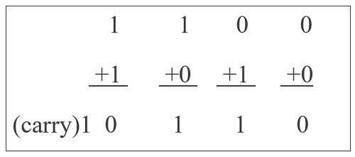
In the first three operations, each binary addition gives sum as one bit , i.e., either 0 or 1. But for the fourth addition operation (where the inputs are 1 and 1), the result consists of two binary digits. Here, the lower significant bit is called as the ‘Sum Bit’, while the higher significant bit is called as the ‘Carry Bit’.
For single bit additions, there may not be an issue. The problem may arise when we try to add binary numbers with more than one bit.
The logic circuits which are designed to perform the addition of two binary numbers are called as Binary Adder Circuits. Depending on how they handle the output of the ‘1+1’ addition, they are divided into:
- Half Adder
- Full Adder
Let us take a look at the binary addition performed by various adder circuits.
Half Adder
A logic circuit used for adding two 1-bit numbers or simply two bits is called as a Half Adder circuit. This circuit has two inputs and two outputs. The inputs are the two 1-bit binary numbers (known as Augend and Addend) and the outputs are Sum and Carry.
The following image shows the block diagram of Half Adder.
The truth table of the Half Adder is shown in the following table.
| INPUT | OUTPUT | ||
| A | B | Sum | Carry |
| 0 | 0 | 0 | 0 |
| 0 | 1 | 1 | 0 |
| 1 | 0 | 1 | 0 |
| 1 | 1 | 0 | 1 |
If we observe the ‘Sum’ values in the above truth table, it resembles an Ex-OR Gate. Similarly, the values for ‘Carry’ in the above truth table resembles an AND Gate.
So, to properly implement a Half Adder, you need two Logic Gates: an XOR gate for ‘Sum’ Output and an AND gate for ‘Carry’ output. The following image shows the Logic Diagram of a Half Adder.
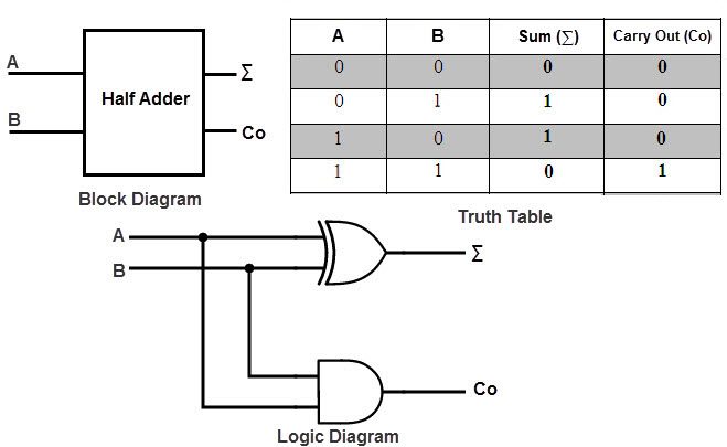
In the above half adder circuit, inputs are labeled as A and B. The ‘Sum’ output is labeled as summation symbol (∑) and the Carry output is labeled with CO.
Half adder is mainly used for addition of augend and addend of first order binary numbers i.e., 1-bit binary numbers. We cannot add binary numbers with more than one bit as the Half Adder cannot include the ‘Carry’ information from the previous sum.
Due to this limitation, Half Adder is practically not used in many applications, especially in multi-digit addition. In such applications, carry of the previous digit addition must be added along with two bits; hence it is a three bit addition.
Full Adder
A Full Adder is a combinational logic circuit which performs addition on three bits and produces two outputs: a Sum and a Carry. As we have seen that the Half Adder cannot respond to three inputs and hence the full adder is used to add three digits at a time.
It consists of three inputs, of which two are input variables representing the two significant bits to be added, whereas the third input terminal is the carry from the previous addition. The two outputs are a Sum and Carry outputs.
The following image shows a block diagram of a Full Adder where the inputs are labelled as A, B and CIN, while the outputs are labelled as ∑ and COUT.
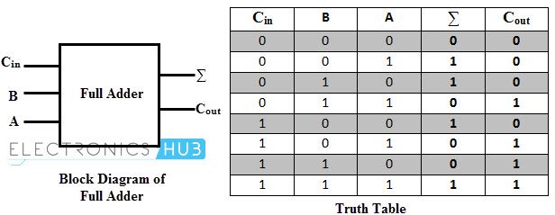
Coming to the truth table, the following table shows the truth table of a Full Adder.
| INPUT | OUTPUT | |||
| A | B | CIN | Sum | COUT |
| 0 | 0 | 0 | 0 | 0 |
| 0 | 0 | 1 | 1 | 0 |
| 0 | 1 | 0 | 1 | 0 |
| 0 | 1 | 1 | 0 | 1 |
| 1 | 0 | 0 | 1 | 0 |
| 1 | 0 | 1 | 0 | 1 |
| 1 | 1 | 0 | 0 | 1 |
| 1 | 1 | 1 | 1 | 1 |
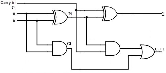
From the above truth table, we can obtain the Boolean Expressions for both the Sum and Carry Outputs. Using those expressions, we can build the logic circuits for Full Adder. But by simplifying the equations further, we can derive at a point that a Full Adder can be easily implemented using two Half Adders and an OR Gate.
The following image shows a Full Adder Circuit implemented using two Half Adders and an OR Gate. Here, A and B are the main input bits, CIN is the carry input, ∑ and COUT are the Sum and Carry Outputs respectively.
Parallel Binary Adders
As we discussed, a single Full Adder performs the addition of two one bit numbers and also the carry input. For performing the addition of binary numbers with more than one bit, more than one full adder is required and the number of Full Adders depends on the number bits. Thus, a Parallel Adder, is a combination of Multiple Full Adders and is used for adding all bits of the two numbers simultaneously.
By connecting ‘n’ number of full adders in parallel, an n-bit Parallel Adder can be constructed. From the below figure, it is to be noted that there is no carry at the least significant position, hence we can use either a half adder or make the carry input of full adder as zero at this position.
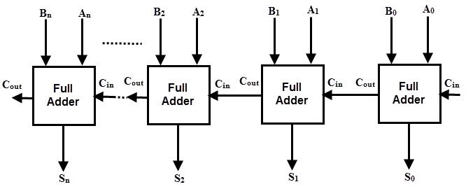
The following figure shows a Parallel 4-bit Binary Adder, which has three full adders and one half adder. The two binary numbers to be added are ‘A3 A2 A1 A0‘ and ‘B3 B2 B1 B0‘ , which are applied to the corresponding inputs of the Full Adders. This parallel adder produces their result as ‘C4 S3 S2 S1 S0‘ , where C4 is the final carry.
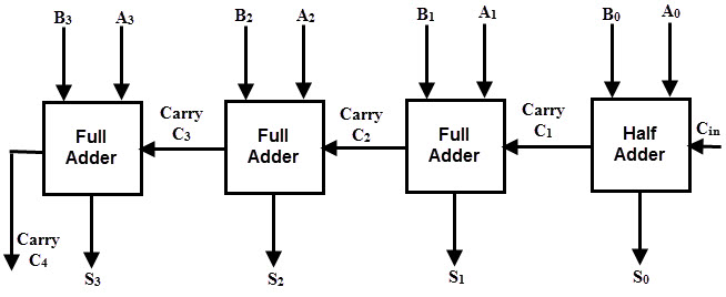
In the 4 bit adder, first block is a half-adder that has two inputs as A0 B0 and produces a sum S0 and a carry bit C1. The first block can also be a full adder and if so, then the input Carry C0 must be 0.
Next three blocks should be full adders, as there are three inputs applied to them (two main binary bits and a Carry bit from the previous stage).
Hence, the second block full adder produces a sum S1 and a carry C2. This will be followed by other two full adders and thus the final result is C4 S3 S2 S1 S0.
Commonly, the Full Adders are designed in dual in-line package integrated circuits. 74LS283 is a popular 4-bit full adder IC. Arithmetic and Logic Unit or ALU of an unit computer consist of these parallel adders to perform the addition of binary numbers.
Binary Subtraction Circuits
Another basic arithmetic operation to be performed by Digital Computers is the Subtraction. Subtraction is a mathematical operation in which one integer number is deducted from another to obtain the equivalent quantity. The number from which other number is to be deducted is called as ‘Minuend’ and the number subtracted from the minuend is called ‘Subtrahend’.
Similar to the binary addition, binary subtraction is also has four possible basic operations. They are:
- 0 – 0 = 0
- 0 – 1 = (Borrow)1 1
- 1 – 0 = 1
- 1 – 1 = 0
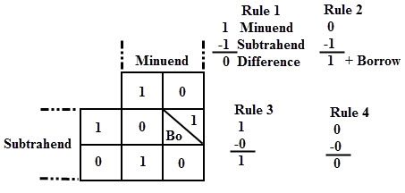
The above figure shows the four possible rules or elementary operations of the binary subtractions. In all the operations, each subtrahend bit is deducted from the minuend bit.
But in the second rule, minuend bit is smaller than the subtrahend bit, hence 1 is borrowed to perform the subtraction. Similar to the adder circuits, basic subtraction circuits are also of two types:
- Half Subtractor
- Full Subtractor
Half Subtractors
A Half Subtractor is a multiple output Combinational Logic Circuit that does the subtraction of two 1-bit binary numbers. It has two inputs and two outputs. The two inputs correspond to the two 1-bit binary numbers and the two outputs corresponds to the Difference bit and Borrow bit (in contrast to Sum and Carry in Half Adder).
The following image shows the block diagram of a Half Subtractor.
Image
Following table shows the truth table of a Half Subtractor.
| INPUT | OUTPUT | ||
| A | B | Difference | Borrow |
| 0 | 0 | 0 | 0 |
| 0 | 1 | 1 | 1 |
| 1 | 0 | 1 | 0 |
| 1 | 1 | 0 | 0 |
From the above truth table, we can say that the ‘Difference’ output of the Half Subtractor is similar to an XOR output (which is also same as the Sum output of the Half Adder). Thus, the Half Subtraction is also performed by the Ex-OR gate with an AND gate with one inverted input and one normal input, requiring to perform the Borrow operation.
The following image shows the logic circuit of a Half Adder.
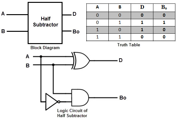
This circuit is similar to that of the Half Adder with only difference being the minuend input i.e., A is complemented before applied at the AND gate to implement the borrow output.
In case of multi-digit subtraction, subtraction between the two digits must be performed along with borrow of the previous digit subtraction, and hence a subtractor needs to have three inputs, which is not possible with a Half Subtractor. Therefore, a half subtractor has limited set of applications and strictly speaking, it is not used in practice.
Full Subtractor
A Full Subtractor is a combinational logic circuit which performs a subtraction between the two 1-bit binary numbers and it also considers the borrow of the previous bit i.e., whether 1 has been borrowed by the previous minuend bit.
So, a Full Subtractor has three inputs, in which two inputs corresponding to the two bits to be subtracted (minuend A and subtrahend B), and a borrow bit, usually represented as BIN, corresponding to the borrow operation. There are two outputs, one corresponds to the difference D output and the other Borrow output BO.
The following image shows the block diagram of a full subtractor.
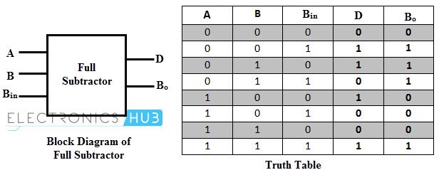
The following table shows the truth table of a Full Subtractor.
| INPUT | OUTPUT | |||
| A | B | BIN | D | BOUT |
| 0 | 0 | 0 | 0 | 0 |
| 0 | 0 | 1 | 1 | 1 |
| 0 | 1 | 0 | 1 | 1 |
| 0 | 1 | 1 | 0 | 1 |
| 1 | 0 | 0 | 1 | 0 |
| 1 | 0 | 1 | 0 | 0 |
| 1 | 1 | 0 | 0 | 0 |
| 1 | 1 | 1 | 1 | 1 |
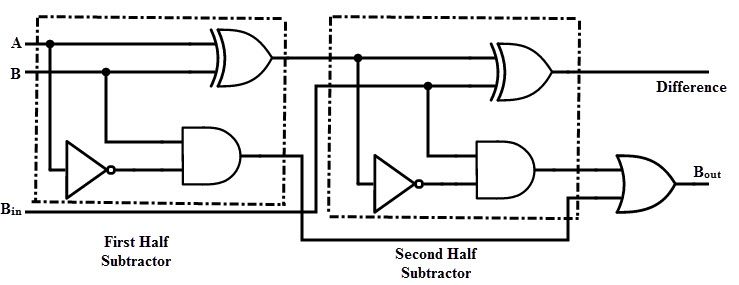
By deriving the Boolean expression for the full subtractor from above truth table, we get the expression that tells that a full subtractor can be implemented with half subtractors with OR gate as shown in figure below.
By comparing the adder and subtractor circuits and truth tables, we can observe that the output D in the full subtractor is exactly same as the output S of the full adder. And the only difference is that input variable A is complemented in the full subtractor.
Therefore, it is possible to convert the full adder circuit into full subtractor by simply complementing the input A before it is applied to the gates to produce the final borrow bit output Bo.
Parallel Binary Subtractors
To perform the subtraction of binary numbers with more than one bit, we have to use the Parallel Subtractors. This parallel subtractor can be designed in several ways, including combination of half and full subtractors, all full subtractors, all full adders with subtrahend complement input, etc.
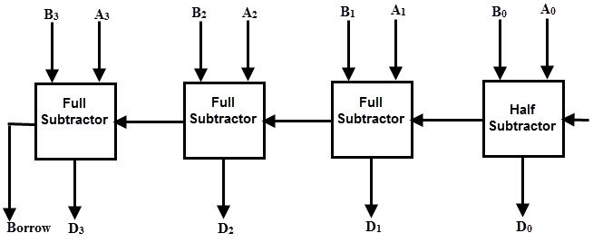
The below figure shows a 4 bit Parallel Binary Subtractor formed by connecting one half subtractor and three full subtractors.
In this subtractor, 4 bit minuend ‘A3 A2 A1 A0‘ is subtracted by 4 bit subtrahend ‘B3 B2 B1 B0‘ and the result is the difference output ‘D3 D2 D1 D0‘ . The borrow output of each subtractor is connected as the borrow input to the next subtractor.
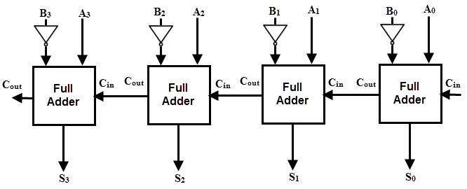
It is also possible to design a 4 bit parallel subtractor using 4 full adders as shown in the below figure. This circuit performs the subtraction operation by considering the principle that the addition of minuend and the complement of the subtrahend is equivalent to the subtraction process.
We know that the subtraction of A by B is obtained by taking 2’s complement of B and adding it to A. The 2’s complement of B is obtained by taking 1’s complement and adding 1 to the least significant pair of bits.
Hence, in this circuit 1’s complement of B is obtained with the inverters (NOT gate) and a 1 can be added to the sum through the input carry.
Parallel Adder / Subtractor
The operations of both addition and subtraction can be performed by a one common binary adder. Such binary circuit can be designed by adding an Ex-OR gate with each full adder as shown in below figure. The figure below shows the 4 bit parallel binary adder/subtractor which has two 4 bit inputs as ‘A3 A2 A1 A0‘ and ‘B3 B2 B1 B0‘ .
The mode input control line M is connected with carry input of the least significant bit of the full adder. This control line decides the type of operation, whether addition or subtraction.
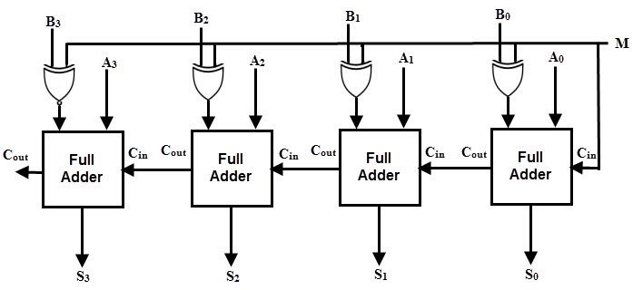
When M= 1, the circuit is a subtractor and when M=0, the circuit becomes adder. The Ex-OR gate consists of two inputs to which one is connected to the B and other to input M. When M = 0, B Ex-OR of 0 produce B. Then, full adders add the B with A with carry input zero and hence an addition operation is performed.
When M = 1, B Ex-OR of 0 produce B complement and also carry input is 1. Hence the complemented B inputs are added to A and 1 is added through the input carry, nothing but a 2’s complement operation. Therefore, the subtraction operation is performed.
Conclusion
A complete beginner’s tutorial on Binary Adders and Subtractors. You learned different binary adder circuits like Half Adder, Full Adder, Parallel Adder and different binary subtractors like Half Subtractor, Full Subtractor, Parallel Subtractor and also a Combination Parallel Adder / Subtractor circuit.

17 Responses
thank you
great.. very explicit! Thanks (y)
Thanks, it’s really been useful
Thank you so much
It’s really been useful and relevant Thanks.
Thank you so much
thank you so much
Really helpful! used this to build a calculator in minecraft lol
Me too!
what if B>A and Cout generated is ‘0’ in case of subtraction, S3S2S1S0, is the 2’s complement of the actual output.
in that case, this circuit won’t actually depict subtraction for all cases, it is limited for A>B subtraction
thanks i appreciate that
Thank you so much for this. I found a way to make a transistor in minecraft and this site has really helped me with my current calculator project. Now I just need to figure out a way to make it convert from decimal to binary and back.
Thank you for the definitions ! Very much satisfied ! Easy to understand
thank you so much
that was sooooo goood thank you !
Excellent ! Clear and to the point, without all the extra (only to impress) BS.
Comment by “Belal Igbal” has a has a valid point. the borrow-in is necessary when (B > A)
very detailed