A binary multiplier is a combinational logic circuit used in digital systems to perform the multiplication of two binary numbers. These are most commonly used in various applications especially in the field of digital signal processing to perform the various algorithms.
Commercial applications like computers, mobiles, high speed calculators and some general purpose processors require binary multipliers.
Compared with addition and subtraction, multiplication is a complex process. In multiplication process, the number which is to be multiplied by the other number is called as multiplicand and the number multiplied is called as multiplier.
Binary Multiplication
Similar to the multiplication of decimal numbers, binary multiplication follows the same process for producing a product result of the two binary numbers. The binary multiplication is much easier as it contains only 0s and 1s. The four fundamental rules for binary multiplication are
0 × 0 = 0
0 × 1 = 0
1 × 0 = 0
1 × 1 = 1
The multiplication of two binary numbers can be performed by using two common methods, namely partial product addition and shifting, and using parallel multipliers.
Before discussing about the types, let us look at the unsigned binary numbers multiplication process. Consider a two 4 bit binary numbers as 1010 and 1011, and its multiplication of these two is given as

From the above multiplication, partial products are generated for each digit in the multiplier. Then all these partial products are added to produce the final product value. In the partial product multiplication, when the multiplier bit zero, the partial product is zero, and when the multiplier bit is 1, the resulted partial product is the multiplicand.
As similar to the decimal numbers, each successive partial product is shifted one position left relative to the preceding partial product before summing all partial products.
Therefore, this multiplication uses n-shifts and adds to multiply n-bit binary number. The combinational circuit implemented to perform such multiplication is called as an array multiplier or combinational multiplier.
Parallel Binary Multiplier Circuit
Let us consider two unsigned 2 bit binary numbers A and B to generalize the multiplication process. The multiplicand A is equal to A1A0 and the multiplier B is equal to B1B0. The figure below shows the multiplication process of two 2 bit binary numbers.
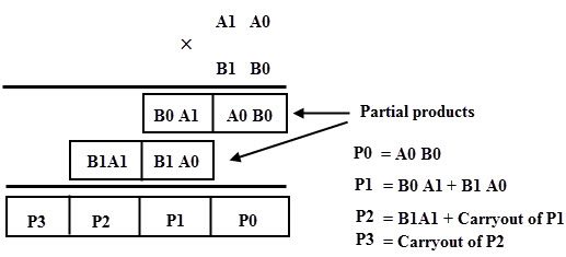
This process involves the multiplication of two digits and the addition of digits with or without carry. After the multiplication of the each bit to the multiplicand, partial products are generated, and then these products are added to produce the total sum which represents the binary multiplication value.
This multiplication is implemented by combinational circuit such that the multiplication is performed with AND gates whereas the addition is carried out by using half adders as shown in figure.
The first partial product is obtained by the AND gate which is nothing but a least significant bit of the multiplication result. Since the second partial product is shifted to the left position, the first partial second term and second partial product first term is added by half adder and produce the sum output along with the carry out.
This carry out is added at the next half adder as an input as shown in figure. Likewise, it produces the multiplication result of two binary numbers by using the simple circuit configuration. The multiplication of the two 2 bit number results a 4-bit binary number.
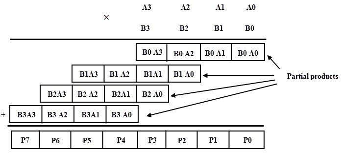
Let us consider two unsigned 4 bit numbers multiplication in which the multiplicand, A is equal to A3A2 A1A0 and the multiplier B is equal to B3B2B1B0. The partial products are produced depending on each multiplier bit multiplied by the multiplicand.
Each partial product consists of four product terms and these are shifted to the left relative to the previous partial product as shown in figure. All these partial products are added to produce the 8 bit product.
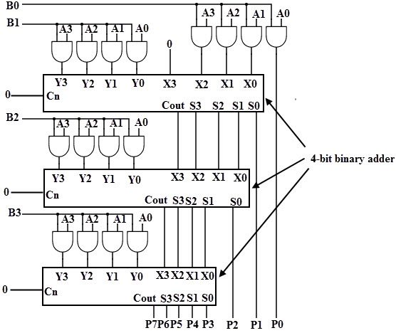
The logic circuit for the 4× 4 binary multiplication can be implemented by using three binary full adders along with AND gates.
In the above operation the first partial product is obtained by multiplying B0 with A3A2 A1A0, the second partial product is formed by multiplying B1 with A3A2 A1A0, likewise for 3rd and 4th partial products. So these partial products can be implemented with AND gates as shown in figure.
These partial products are then added by using 4 bit parallel adder. The three most significant bits of first partial product with carry (considered as zero) are added with second partial term in the first full adder.
Then the result is added to the next partial product with carry out and it goes on till the final partial product, finally it produces 8 bit sum which indicates the multiplication value of the two binary numbers.
Binary Multiplier Using Shift Method
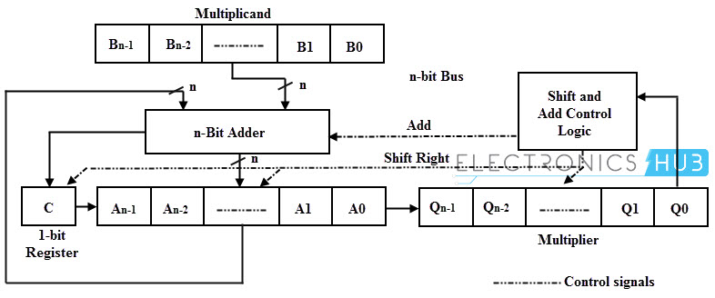
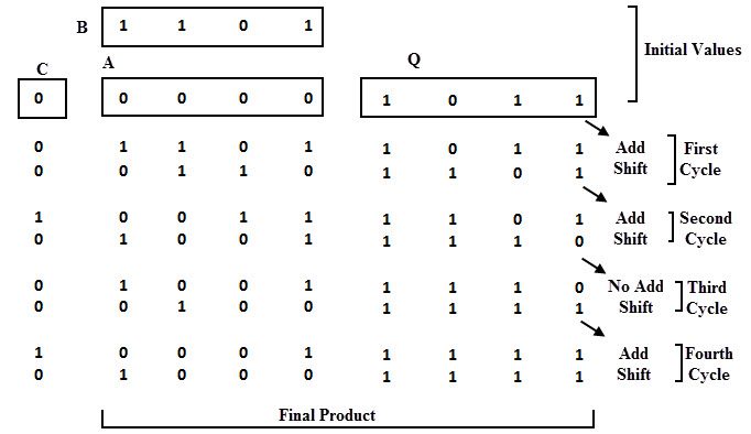
Alternatively to the above automated method, manual multiplication approach can be implemented by using n-bit adder, four registers (A, B, C and Q) and shift and control logic as shown in below figure.
In this, the 4 bit multiplier is stored in Q register, the 4 bit multiplicand is stored in register B and the register A is initially cleared to zero. The multiplication process starts with checking of the least significant bit of B whether it is 0 or 1.
If the B0 = 1, the number in the multiplicand (B) is added with the least significant bits of the A register and all bits of C, A and Q registers are shifted to the right one bit.
If the bit B0 = 0, the combined C and Q registers are shifted to the right by one bit without performing any addition. This process is repeated for n times for n bit numbers. This method of binary multiplication is called as parallel multiplier.
Consider the below figure in which the multiplier and multiplicand values are given as 1011 and 1101 which are loaded into the Q and A registers respectively. Initially the register C is zero and hence the A register is zero, which stores the carry in addition.
Since the B0 =1, then the number in the B is added to the bits of A and produce the addition result as 1101, and the Q and A register are shifted their values one bit right so the new values during the first cycle are 0110 and 1101 respectively.
This process has to be repeated four times to perform the 4 bit multiplication. The final multiplication result will be available in the A and Q registers as 10001111 as shown in the figure.
A 4 × 4 unsigned binary multiplier takes two, four bit inputs and produces an output of 8 bits. Similarly 8 × 8 multiplier accepts two 8 bit inputs and generates an output of 16 bits.
These multiplier logic circuits are implemented on integrated circuits with various pin configurations.
These ICs are used in several applications, particularly in various microprocessors used for computers, controlling devices, calculators, mobiles, digital signal processors (DSPs), etc.
