In this project, we will learn about the one-wire Digital Temperature Sensor DS18B20 and how the Arduino DS18B20 interface works.
Temperature Sensors are very important devices as they help us in measuring, monitoring and maintaining the temperature of a room, instrument or a device.
Previously we have used the very popular LM35 Temperature Sensor in almost every temperature related project. We will now try a different Temperature Sensor called DS18B20 to measure the temperature using Arduino.
Related Project: Arduino based Digital Thermometer
Overview of DS18B20 Temperature Sensor
DS18B20 is a 1-Wire (one-Wire) Temperature Sensor produced by Maxim Integrated. It provides the temperature measurements in Degree Celsius with a resolution of 9-bit to 12-bit.
The DS18B20 Temperature exchanges information over 1-Wire Interface or 1-Wire Bus, a system developed by Dallas Semiconductor. In 1-Wire Interface, the communication requires only one wire (well, technically you need two wires: one data wire and one GND wire).
Another important feature of DS18B20 Temperature Sensor is that every DS18B20 Sensor comes with a 64-bit serial code that is specific to that sensor.
Using this unique code, you can connect many DS18B20 Sensors on the same 1-Wire Bus and access the information using a single controller. This type of setup can be useful in situations where multiple DS18B20 Sensors are distributed over a huge area.
The following are few of the main features of DS18B20 Digital Thermometer.
- Uses 1-Wire Interface that requires only one wire for data transfer.
- Programmable Resolution of 9-bit to 12-bit.
- It can measure temperatures in the range of -55 0C to +125 0C.
- Available in different packages like TO-92, 8-Pin SO and 8-Pin µSOP.
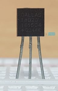
Pin Diagram of DS18B20
The following image shows the Pin diagram of the DS18B20 Digital Temperature Sensor in its TO-92 Package.
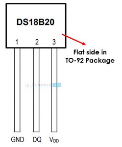
Pin Description of DS18B20 Temperature Sensor
As you can see in the above pin diagram, the DS18B20 Sensor consists of three pins namely: VDD, DQ and GND.
VDD: This is the power supply pin. It must be grounded when parasite power mode is used (more about this later).
DQ: This is the Data Input/Output Pin. It is an open-drain pin and must pulled HIGH. It provides the power in parasite power mode.
GND: This is the Ground Pin.
Block Diagram of DS18B20
The following image shows the functional block diagram of the DS18B20 Temperature Sensor. It consists of a power supply circuit, 64-bit ROM, Memory Controller, the main Temperature Sensor and a Scratchpad area which has a temperature register and few other registers for storing configuration and alarm High and Low triggers.

64-bit ROM stores the unique serial code of the device. The digital output from the temperature sensor is stored in the 2-Byte Temperature Register of the Scratchpad. The scratchpad also consists of 1-Byte for Alarm HIGH Trigger register, Alarm LOW Trigger register and Configuration register each.
Using the configuration register, you can set the resolution of the digital output from anywhere between 9-bits to 12-bits. To retain the data stored in the configuration, Alarm High and Alarm Low registers even when the device is powered down, these three registers are implemented as EEPROM.
Powering the DS18B20 Sensor
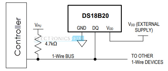
There are two ways you can power up the DS18B20 Sensor. One way is the traditional way of connecting an external power supply to the VDD Pin of the sensor. There is nothing special about this operation.
The second method of powering on the DS18B20 sensor is what makes things interesting. The second way of powering the sensor is called Parasite Power Mode, where there is no need for an external power supply.
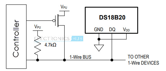
In Parasite Power Mode, the DS18B20 draws power from the DQ pin when it is pulled HIGH. When the 1-Wire Bus is High, it powers the DS18B20. When the Bus is Low, the charge stored in the Parasite Power Capacitor (CPP) will power the sensor. In Parasite Power Mode, the VDD pin is connected to GND.
Interfacing DS18B20 with Arduino
In this project, we will see how to interface the DS18B20 Temperature Sensor with Arduino. Since the sensor is based on 1-Wire Communication, it requires only one wire between Arduino and DS18B20.
Circuit Diagram of Arduino DS18B20 Interface
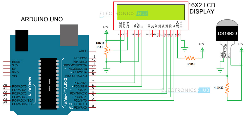
The following image shows the circuit diagram of the Arduino DS18B20 Interface.
Components Required
- Arduino UNO
- DS18B20 Digital Temperature Sensor
- 16×2 LCD Display
- 10KΩ Potentiometer
- 4.7KΩ Resistor (1/4 Watt)
- 330Ω Resistor (1/4 Watt)
- 5mm LED
- Connecting Wires
- Breadboard
- Power Supply
Circuit Design
The design of the Arduino DS18B20 Interface Circuit is very simple. All you need is to connect the VDD and GND of the sensor to +5V and GND and connect the DQ Pin of the Sensor to any one of the Digital I/O Pin (it is connected to Digital I/O Pin 8).
The DQ pin is pulled HIGH using a 4.7KΩ resistor.
Since we need to view the measured temperature, I have connected a simple 16X2 LCD display to Arduino.
Code
The code for the project is given below. You need to download two libraries for Arduino: OneWire and DallasTemperature. You can download these libraries from the following links: Download OneWire Library and Download DallasTemperature Library.
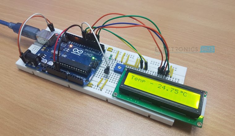
Working of the Arduino DS18B20 Interface
The working of the project is very simple. Arduino communicates with DS18B20 over 1-Wire Interface and extracts the temperature information from the sensor. The extracted information is displayed on the 16X2 LCD Display.
Applications
The DS18B20 Temperature Sensor can be used in a variety of applications like:
- Thermometers
- Temperature Sensitive Systems
- Consumer Electronics
- Industrial Equipment
- Thermostats

One Response
Thanks for the marvelous posting! I certainly enjoyed reading it,
you will be a great author.I will ensure that I bookmark your blog and definitely will come back in the future.
I want to encourage yourself to continue your great posts, have
a nice day!