An Inductor is usually a coil of wire that sets up an alternating magnetic field around it when an alternating current flows through it .Inductance is the property of an inductor that opposes the change in current. It is measured in Henry. Due to this inductance , a back emf is induced in the coil when it is subjected to an alternating current.
According to the Lenz’s law, this emf opposes the change in the current. Therefore, the applied voltage has to overcome this back emf only, because there is no resistance in the circuit. Thus, the applied voltage and back emf are should be equal and opposite to keep the current flowing through the circuit.
The AC circuit behavior with inductor is entirely different from the DC circuit. In this the current flowing through the coil depends not only on the inductance but also on frequency of the alternating source. Let us discuss the behavior of AC circuit with inductive loads in brief.
AC Applied Across a Pure Inductor
A pure inductor has no resistance in the coil winding but has only inductance. This property of inductance is exhibited by all motors, transformers and generators (with some resistance in the coil). The figure below shows pure inductive circuit with AC voltage source and their appropriate waveforms.
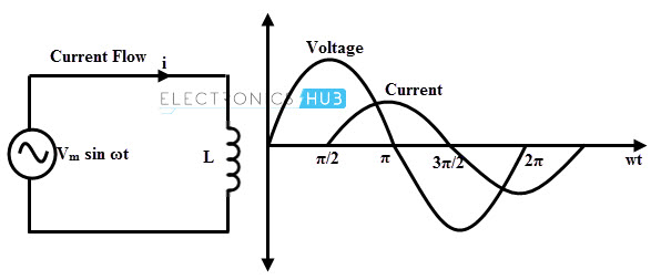
Let the applied voltage, v = Vm sin ωt. As stated above that the emf induced is equal and opposite to the applied voltage, i.e., v = – e
Where e is the back emf and is equal to –L di/dt
Substituting the emf expression, we get
v = L di/dt
Vm sin ωt = L di/dt
di = (Vm / L) sin ωt dt
By applying integration on both sides, we get
i = (Vm / L) ∫ sin ωt dt
= (Vm / ωL) (– cos ωt)
i = (Vm / wL) (sin ωt – π/2)
When (sin ωt – π/2) is unity, the current flowing through the circuit will be maximum. So
im = (Vm / ωL)
Then the current equation becomes,
i = im sin (ωt – π/2)
Where im = (Vm / ωL)
From the above current and voltage expressions, it is clear that the current lags the voltage by 900. Therefore, in pure inductive circuit current is in quadrature with the voltage as shown in waveforms of the above figure.
This means that when the change in the current is maximum (at current passing through zero), the voltage induced across the inductor is maximum. Similarly, at maximum values of current where current is not changing, the induced voltage across the inductor will be zero.
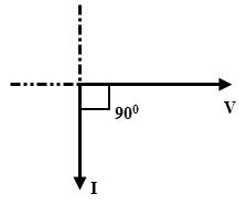
Thus, the voltage across an inductor leads the current through that inductor by ¼ (quarter) cycle. The phasor diagram of a pure inductive AC circuit is given below.
Inductive Reactance
From the above derivation, the maximum current equation is given as
im = (Vm / ωL)
ωL = Vm / im
This ratio of voltage to current is the opposition offered by the inductive circuit to the current flow. This wL quantity is termed as inductive reactance and it is denoted as XL, measured in Ohms.
The inductive reactance of the AC circuit can be represented as
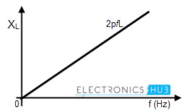
XL = ωL = 2ΠfL (since ω = 2Πf)
Where XL is the inductive reactance in Ohm’s
f is the frequency of the supply voltage
L is the inductance of the coil in Henry
The above equation tells that when the frequency of the input supply increases, the rate at which current changes also gets varied. Hence, the induced emf (or reacting voltage) across the inductor will be increased.
As a result, the net current flowing through the inductor will be reduced. It is to be concluded that reactance of the inductor varies linearly with frequency of the supply as shown in figure.
Power and Power Factor in Inductive AC Circuit
The power in an AC circuit is the product of instantaneous voltage and current. This can be given as
P = v × i
P = Vm sin ωt × Im sin (ωt – 90)
Taking integration over a cycle we get,
P = Vm sin ωt × Im sin (ωt – 90)
P = 1/2π (∫02π Vm sin ωt × Im sin (ωt – 90) dωt)
= (Vm Im / 2π) (∫02π sin ωt × (– cos ωt) dwt)
= (Vm Im / 2π) (∫02π (– sin 2 ωt)/2 dwt)
= (Vm Im / 8π) (cos 4π – cos 0)
= (Vm Im / 8π) (1 – 1)
P =0
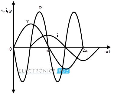
The average power in a pure inductor always zero because the amount of energy received from the source in a half-cycle is returned to the source in the next half-cycle.
The below figure shows the power curve of the inductive AC circuit in which positive power is equal to the negative power, so the resultant power over a cycle is zero. This clearly explains that no power is consumed by the pure inductance.
In this circuit, current is also sinusoidal, but lagging behind the voltage by 900. Since the current lags the voltage by 900, the phase difference, θ is equal to 900. Then
The power factor, cos 90 = 0
The power factor in a pure inductive circuit is zero, i.e., pure lagging power factor.
Series RL Circuit
As we know that there is no pure inductance physical circuit because every coil has some winding resistance along with inductance. In such circuit, resistance is considered as series element to the inductor.
Consider the below figure in which a pure resistance is connected in series with pure inductance. This series combination is connected across an AC supply of voltage v = Vm sin ωt.
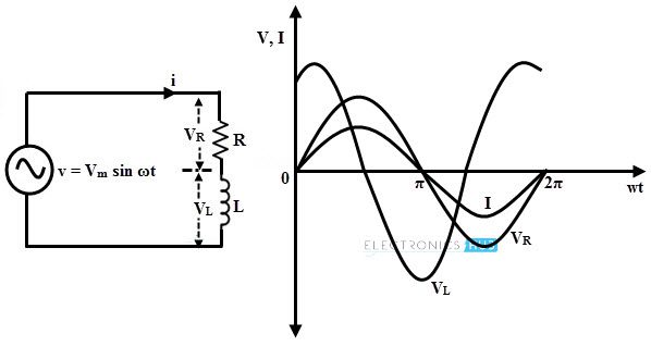
In series RL circuit, the voltage across the inductor is out of phase with both current flowing through the circuit and voltage across the resistance as shown in above figure. The induced voltage in the inductor opposes the flow of current and hence VL leads the current I and drop across resistance VR by 900.
Let I be the current flowing through the circuit, VL and VR are the voltage drops across inductance and resistance respectively.
Voltage across the resistor, VR = IR
Voltage across the inductor, VL = I × XL (where XL = 2πfL)
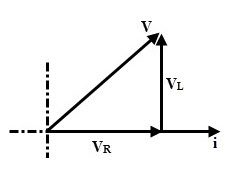
From the above phasor,
V = √ (VR2 + VL2) = √ (IR)2+ (I XL)2)
= I √ (R2 + XL2) = IZ
Where Z is the impedance in RL series circuit and is equal to √ (R2 + XL2).
Impedance Triangle
The opposition offered by the AC circuit to the flow of sinusoidal current is called as impedance. It can also be defined as the ratio of sinusoidal voltage to the current. It is denoted by the letter Z and is measured in Ohms.
From the RL series phasor diagram,
tan ϕ = VL / VR = XL / R
cos ϕ = VR / V = R / Z
sin ϕ = VL / V = XL / Z
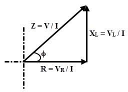
If all sides of the triangle obtained in XL series circuit is divided by current, we get impedance triangle as shown in figure. From this triangle R, XL and Z components can be expressed as
R = Z cos ϕ
XL = Z sin ϕ
Z = √ (R2 + XL2)
And ϕ = tan-1 (XL / R)
Example
Find an expression for current and also calculate the power of an RL series circuit having R = 50 Ohms and L = 0.159 H, excited with a voltage of v = 283 sin 100πt.
Inductive reactance, XL = 2πfL = 100π × 0.159
= 49.95 Ohm
Z = R + j XL = 50 + j49.95
Converting into polar form, we get Z = 70.675 ∠44.97 Ohm
Current, i = v/ Z = (283 sin (100πt – 44.97))/ 70.675
i = 4 sin (100πt – π/4) A
P = VI cos θ
= (283/ √2) (4/√2) cos 44.97
= 400.43 A
