Due to the advantages like good frequency stability, very low distortion and ease of tuning, a Wien bridge oscillator becomes the most popular audio frequency range signal generator circuit. This type of oscillator uses RC feedback network so it can also be considered as RC oscillator.
The main difference between the general oscillator and Wien bridge oscillator is that in an oscillator, amplifier stage introduces 180 degrees phase shift and additional 180 degrees phase shift is introduced by feedback network so as to obtain the 360 degrees or zero phase shift around the loop to satisfy the Barkhausen criteria.
But, in case of the Wien bridge oscillator, a non inverting amplifier used in amplifier stage does not introduce any phase shift. Hence there is no need of phase shift through feedback network is required in order to satisfy the Barkhausen criteria. Let us discuss in brief about Wien bridge oscillator.
Wien Bridge Oscillator
A Wien bridge oscillator produces sine waves which uses RC network as the frequency determining portion of the circuit. A basic circuit of Wien bridge oscillator with amplifier stage is shown in below figure.
The output of the amplifier is applied between the terminals 1 and 3 while the input to the amplifier stage is supplied from terminals 2 and 4 hence the amplifier output becomes input voltage of the bridge whilst the output of the bridge becomes the input voltage of the amplifier.

When the bridge is balanced the input voltage to the amplifier becomes zero, so in order to produce the sustained oscillations input to the amplifier must be non-vanishing. Therefore the bridge is unbalanced by adjusting the proper values of the resistors.
As we mentioned above the RC network is responsible for determining the frequency of the oscillator. This RC network consists of two frequency sensitive arms namely series R1C1 and parallel R2, C2. This network is also called as lead-lag circuit.
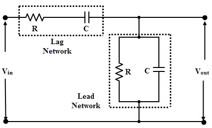
The output voltage across the capacitor lags behind the input voltage by an angle between 0 to – 90 degrees in the lag circuit. In the lead circuit, the output voltage across the resistor leads the input voltage by an angle between 0 and 90 degrees.
At very low frequencies the output voltage becomes zero since the series capacitor behaves as an open circuited and also there is no output at very high frequencies since the parallel capacitor acts as shorted circuited path to the input voltage. Therefore in-between these two extreme conditions, the output voltage reach to the maximum value.
The resonant frequency is the frequency at which the output voltage is maximum. At this frequency, feedback fraction K reaches to a maximum value of 1/3.
The feedback will be maximum when Xc = R and hence the resonant frequency is given by
f = 1 / 2πRC
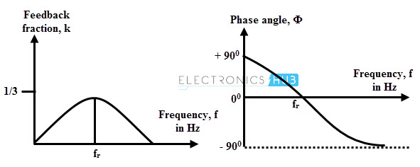
The above figure indicates the output voltage at resonant frequency. At the resonant frequency the phase shift through the circuit is zero and the attenuation V1/V0 is 1/3. Therefore, in order to maintain oscillations, the amplifier must have a gain greater than 3.
The different frequency ranges can be provided by the Wien bridge oscillator by mounting the two capacitors on the shaft and by varying their values simultaneously.
Wien Bridge Oscillator Using Op-amp
The figure below shows a widely used type of Wien bridge oscillator. The operational amplifier is used in a non inverting configuration and feedback form a voltage divider network. The resistances R1 and Rf forms the part of the feedback path which determines or facilitates to adjust the amplifier gain.
The output of op-amp is connected as input to the bridge at points a and c while the output of the bridge at points b and d are connected to the input of op-amp.
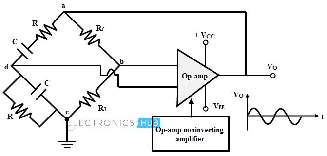
A portion of the amplifier output is feedback through the voltage divider network (a series combination of resistor and capacitor) to the positive or non-inverting terminal of the amplifier.
Also, second portion of the amplifier is feedback to the inverting or negative terminal of the amplifier through the impedance of magnitude 2R.
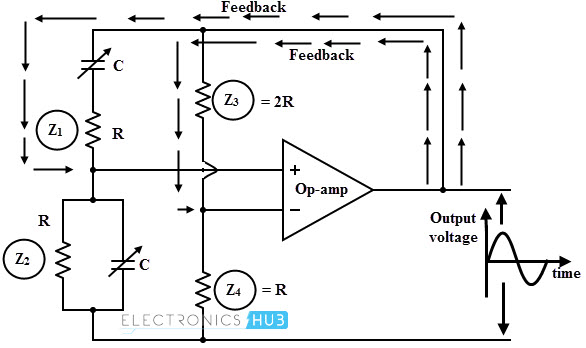
If the feedback network elements are chosen properly, the phase shift of the signal input to the amplifier is zero at certain frequency. Since the amplifier is non-inverting which introduce zero phase shift plus the feedback network zero phase shift, the total phase shift becomes zero around the loop hence the required condition of oscillations.
Therefore the Wien bridge oscillator works as a sine wave generator whose frequency of oscillations is determined by R and C components.
The gain of the operational amplifier is expressed as
A = 1 + (Rf / R1)
As we discussed above that the gain of non-inverting amplifier must be of minimum 3 to satisfy Barkhausen criterion.
Therefore, 1 + (Rf / R1) ≥ 3
→ (Rf / R1) ≥ 2
Therefore the ratio of resistances Rf to R1 must be equal to or greater than 2. The frequency of oscillations is given by
f = 1 / 2πRC
Example Problem on Wien Bridge Oscillator
Determine the RC values of Wien bridge oscillator circuit for the operation at a frequency of 10 kHz if R = 100 K ohms and R1 = 1 K ohm.
Given that f = 10 kHz, R = 100 K ohms, R1 = 1K ohm.
The frequency of oscillations in Wien bridge oscillator is given as
f = 1 / (2πRC)
Then C = 1 /(2π × 100 × 103 × 10 × 103)
= 0.159 nF
For sustained oscillations, gain must be greater than 3, i.e., A ≥ 3
Then 1 + (Rf / R1) ≥ 3
(Rf / R1) ≥ 2
Rf ≥ 1K Ohm
Therefore R and C values are 0.159 nF and 1K Ohm respectively.
Transistorized Wien Bridge Oscillator
The figure below shows the transistorized Wien bridge oscillator which uses two stage common emitter transistor amplifier. Each amplifier stage introduces a phase shift of 180 degrees and hence a total 360 degrees phase shift is introduced which is nothing but a zero phase shift condition.
The feedback bridge consists of RC series elements, RC parallel elements, R3 and R4 resistances. The input to the bridge circuit is applied from the collector of transistor T2 through a coupling capacitor.
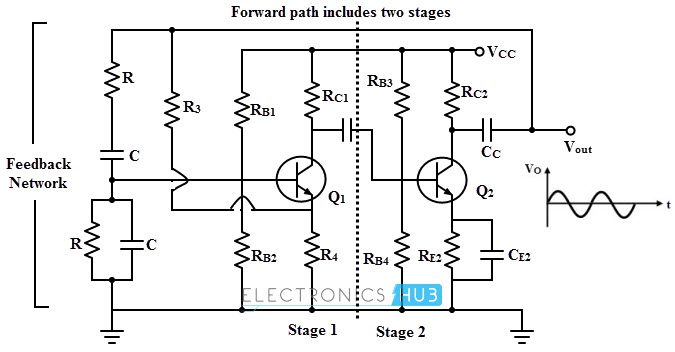
When the DC source is applied to the circuit, a noise signal is at the base of the transistor T1 is generated due to the movement of charge carriers through transistor and other circuit components. This voltage is amplified with gain A and produce output voltage 180 degrees out of phase with input voltage.
This output voltage is applied as input to second transistor at base terminal of T2. This voltage is multiplied with gain of the T2.
The amplified output of the transistor T2 is 180 degrees out of phase with the output of the T1. This output is feedback to the transistor T1 through the coupling capacitor C. So the oscillations are produced at wide range of frequencies by this positive feedback when Barkhausen conditions are satisfied.
Generally, the Wien bridge in the feedback network incorporates the oscillations at single desired frequency.
The bridge is get balanced at the frequency at which total phase shift is zero.
The output of the two stage transistor acts as an input to the feedback network which is applied between the base and ground.
Feedback voltage,Vf = (Vo × R4) / (R3 + R4)
Automatic Gain Control in Wien Bridge
The gain must be of self adjusting for achieving stability for feedback oscillators. This is a form of Automatic Gain Control (AGC). This can be achieved by simply placing a zener diode in parallel with resistor R3 in feedback network. When the output signal reaches to the zener breakdown voltage, zener diode conducts which in turn causes to short out resistance R3.
This decreases the amplifier gain to 3 and hence sustained oscillations produced by the result of total loop gain 1. Although this method of automatic gain control is simple but it suffers from the non-linearity of the zener diode so the sinusoidal wave get distorted.
Another method of controlling the gain is the use of a JFET as a voltage controlled resistance in a negative feedback path. As compared with the zener diode method, this method of gain control produces a stable sinusoidal waveform. A JFET operates in ohmic region with small or zero Vos.
Therefore the drain –source resistance increases with increase of gate voltage. Thus the automatic gain control is achieved by this voltage control resistance when the JFET is placed in negative feedback loop.
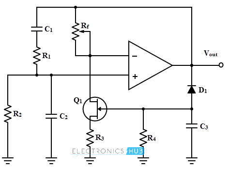
The above figure illustrates the automatic gain control of JFET stabilized Wien bridge oscillator. In this circuit, the amplifier gain is controlled by the components Rf, R3 and Q1. Depends on the gate voltage, the drain-source resistance is varied. This resistance is minimum with gate zero volts. At this, the loop gain will be more than 1.
As the output voltage increases rapidly, negative output signal forward bias the diode and hence capacitor charges to a negative voltage. This charging voltage increases the resistance of the JFET between the drain and source which further leads to reduce the amplifier gain.
By selecting the proper values of feedback components, the loop gain can be stabilized at desired level.
Advantages
- Because of the usage of two stage amplifier, the overall gain of this oscillator is high.
- By varying the values of C1 and C2 or with use of variable resistors, the frequency of oscillations can be varied.
- It produces a very good sine wave with less distortion
- The frequency stability is good
- Due to the absence of inductors, no interference occurs from external magnetic fields.
Disadvantages
- More number of components is needed for two stage amplifier type of Wien bridge oscillators.
- Very high frequencies cannot be generated.

One Response
For the example under Wien-Bridge using Op-Amp , it think Rf >=2K Ohm