In this tutorial, we will learn about some of the basics of TRIAC. In the process, we will understand the structure, symbol, working, characteristics, applications of TRIAC.
Introduction
As we know that the SCR as a unidirectional device and has a reverse blocking characteristics that prevents the current flow in reverse biased condition. But for many applications, bidirectional control of current is required, particularly in AC circuits. To achieve this with SCRs, two SCRs must be connected in anti-parallel to control over both positive and negative half cycles of the input.
However, this structure can be replaced by special semiconductor device known as a TRIAC to accomplish the bidirectional control. The TRIAC is a bidirectional switching device that can control the AC power efficiently and accurately. These are often used in motor speed controllers, AC circuits, pressure control systems, light dimmers and other AC control equipments.
TRIAC Basics
The triac is an important member of the thyristor family of devices. It is a bidirectional device that can pass the current in both forward and reverse biased conditions and hence it is an AC control device. The triac is equivalent to two back to back SCRs connected with one gate terminal as shown in figure.
TRIAC is an abbreviation for a TRIode AC switch. TRI means that the device consisting of three terminals and AC means that it controls the AC power or it can conduct in both directions of alternating current.
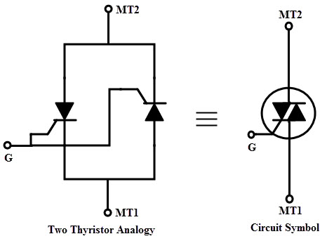
The triac has three terminals namely Main Terminal 1(MT1), Main Terminal 2 (MT2) and Gate (G) as shown in figure. If MT1 is forward biased with respect to MT2, then the current flows from MT1 to MT2. Similarly, if the MT2 is forward biased with respect to MT1, then the current flows from MT2 to MT1.
The above two conditions are achieved whenever the gate is triggered with an appropriate gate pulse. Similar to the SCR, triac is also turned by injecting appropriate current pulses into the gate terminal. Once it is turned ON, it looses its gate control over its conduction. So traic can be turned OFF by reducing the current to zero through the main terminals.
Construction of TRIAC
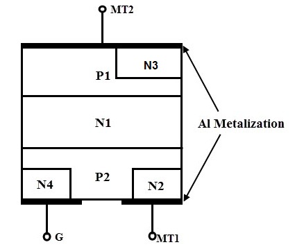
A triac is a five layer, three terminal semiconductor device. The terminals are marked as MT1, MT2 as anode and cathode terminals in case of SCR. And the gate is represented as G similar to the thyristor. The gate terminal is connected to both N4 and P2 regions by a metallic contact and it is near to the MT1 terminal.
The terminal MT1 is connected to both N2 and P2 regions, while MT2 is connected to both N3 and P1 regions. Hence, the terminals MT1 and MT2 connected to both P and N regions of the device and thus the polarity of applied voltage between these two terminals decides the current flow through the layers of the device.
With the gate open, MT2 is made positive with respect to MT1 for a forward biased traic. Hence traic operates in forward blocking mode until the voltage across the triac is less than the forward breakover voltage. Similarly for a reverse biased triac, MT2 is made negative with respect to MT1 with gate open.
Until the voltage across the triac is less than the reverse breakover voltage, device operates in a reverse blocking mode. A traic can be made conductive by either positive or negative voltage at the gate terminal.
Working and Operation of TRIAC
It is possible to connect various combinations of negative and positive voltages to the triac terminals because it is a bidirectional device. The four possible electrode potential combinations which make the triac to operate four different operating quadrants or modes are given as.
- MT2 is positive with respect to MT1 with a gate polarity positive with respect to MT1.
- MT2 is positive with respect to MT1 with a gate polarity negative with respect to MT1.
- MT2 is negative with respect to MT1 with a gate polarity negative with respect to MT1.
- MT2 is negative with respect to MT1 with a gate polarity positive with respect to MT1.
In general, latching current is higher in second quadrant or mode whilst gate trigger current is higher in the fourth mode compared with other modes for any triac.
Most of the applications, negative triggering current circuit is used that means 2 and 3 quadrants are used for a reliable triggering in bidirectional control and also when the gate sensitivity is critical. The gate sensitivity is highest with modes 1 and 4 are generally employed.
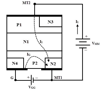
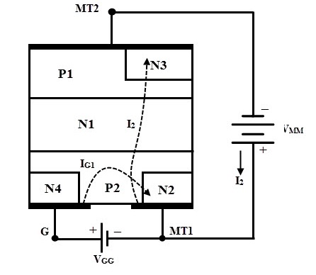
Mode 1: MT2 is Positive, Positive Gate Current
When the gate terminal is made positive with respect to MT1, gate current flows through the P2 and N2 junction. When this current flows, the P2 layer is flooded with electrons and further these electrons are diffused to the edge of junction J2 (or P2-N1 junction).
These electrons collected by the N1 layer builds a space charge on the N1 layer. Therefore, more holes from the P1 region are diffused into the N1 region to neutralize the negative space charges. These holes arrive at the junction J2 and produce the positive space charge in the P2 region, which causes more electrons to inject into P2 from N2.
This results a positive regeneration and finally the main current flows from MT2 to MT1 through the regions P1- N1 – P2 – N2.
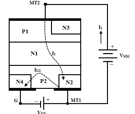
Mode 2: MT2 is Positive, Negative Gate Current
When MT2 is positive and the gate terminal is negative with respect to MT1, gate current flows through the P2-N4 junction. This gate current forward biases the P2-N4 junction for auxiliary P1N1P2N4 structure. This results the triac to conduct initially through the P1N1P2N4 layers.
This further raises the potential between P2N2 towards the potential of MT2. This causes the current to establish from left to right in the P2 layer which forward biases the junction P2N2. And hence the main structure P1N1P2N2 begins to conduct.
Initially conducted auxiliary structure P1N1P2N4 is considered as a pilot SCR while later conducted structure P1N1P2N2 is considered as main SCR. Hence the anode current of pilot SCR serves as gate current to the main SCR. The sensitivity to gate current is less in this mode and hence more gate current is required to turn the triac.
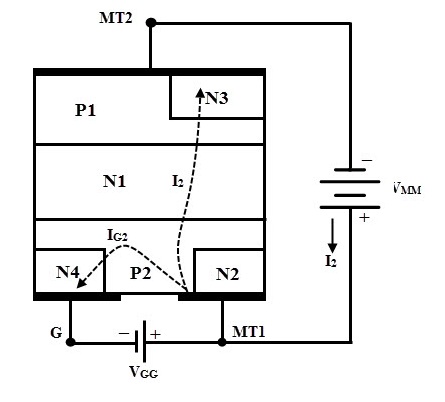
Mode 3: MT2 is Negative, Positive Gate Current
In this mode, MT2 is made negative with respect to MT1 and the device is turned ON by applying a positive voltage between the gate and MT1 terminal. The turn ON is initiated by N2 which acts as a remote gate control and the structure leads to turn ON the triac is P2N1P1N3.
The external gate current forward biases the junction P2-N2. N2 layer injects the electrons into the P2 layer which are then collected by junction P2N1. This result to increases the current flow through P2N1 junction.
The holes injected from layer P2 diffuse through the N1 region. This builds a positive space charge in the P region. Therefore, more electrons from N3 are diffused into P1 to neutralize the positive space charges.
Hence, these electrons arrive at junction J2 and produce a negative space charge in the N1region which results to inject more holes from the P2 into the region N1. This regenerative process continues till the structure P2N1P1N3 turns ON the triac and conducts the external current.
As the triac is turned ON by the remote gate N2, the device is less sensitive to the positive gate current in this mode.
Mode 4: MT2 is Negative, Negative Gate Current
In this mode N4 acts as a remote gate and injects the electrons into the P2 region. The external gate current forward biases the junction P2N4. The electrons from the N4 region are collected by the P2N1 junction increase the current across P1N1 junction.
Hence the structure P2N1P1N3 turns ON by the regenerative action. The triac is more sensitive in this mode compared with positive gate current in mode 3.
From the above discussion, it is concluded that the modes 2 and 3 are less sensitive configuration which needs more gate current to trigger the triac, whereas more common triggering modes of triac are 1 and 4 which have greater sensitivity. In practice the more sensitive mode of operation is selected such that the polarity of the gate is to match with the polarity of the terminal MT2.
V-I Characteristics of TRIAC
The traic function like a two thyristors connected in anti-parallel and hence the VI characteristics of triac in the 1st and 3rd quadrants will be similar to the VI characteristics of a thyristors. When the terminal MT2 is positive with respect to MT1 terminal, the traic is said to be in forward blocking mode.
A small leakage current flows through the device provided that voltage across the device is lower than the breakover voltage. Once the breakover voltage of the device is reached, then the triac turns ON as shown in below figure.
However, it is also possible to turn ON the triac below the VBO by applying a gate pulse in such that the current through the device should be more than the latching current of the triac.
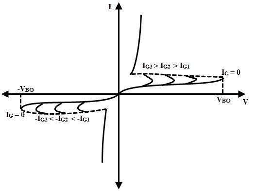
Similarly, when the terminal MT2 is made negative with respect to MT1, the traic is in reverse blocking mode. A small leakage current flows through the device until it is triggered by breakover voltage or gate triggering method. Hence the positive or negative pulse to the gate triggers the triac in both directions.
The supply voltage at which the triac starts conducting depends on the gate current. If the gate is current is being greater, lesser will be the supply voltage at which the triac is turned ON. Above discussed mode -1 triggering is used in the first quadrant whereas mode-3 triggering is used in 3rd quadrant.
Due to the internal structure of the triac, the actual values of latching current, gate trigger current and holding current may be slightly different in different operating modes. Therefore, the ratings of the traics considerably lower than the thyristors.
Advantages
Triac can be triggered by both positive and negative polarity voltages applied at the gate.
- It can operate and switch both half cycles of an AC waveform.
- As compared with the anti-parallel thyristor configuration which requires two heat sinks of slightly smaller size, a triac needs a single heat sink of slightly larger size. Hence the triac saves both space and cost in AC power applications.
- In DC applications, SCRs are required to be connected with a parallel diode to protect against reverse voltage. But the triac may work without a diode, a safe breakdown is possible in either direction.
Disadvantages
- These are available in lower ratings as compared with thyristors.
- A careful consideration is required while selecting a gate trigger circuit since a triac can be triggered in both forward and reverse biased conditions.
- These have low dv/dt rating as compared with thyristors.
- These have very small switching frequencies.
- Triacs are less reliable than thyristors.
Applications
Due to the bidirectional control of AC, triacs are used as AC power controllers, fan controllers, heater controllers, triggering devices for SCRs, three position static switch, light dimmers, etc. Triac as a switch and phase control applications are discussed below.
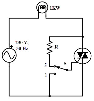
Triac as a High Power Switch
As the triac uses low gate voltage and currents to control the high load voltage and currents, it is often used as switching device in many switching operations. The figure below shows the use of triac as ON/OFF AC switch to control the high power lamp.
When the switch S is at position 1, the triac is in forward blocking mode and hence the lamp remains in OFF state. If the switch is thrown into position 2, a small gate current flows through the gate terminal and hence the triac is turned ON. This further makes the lamp to switch ON to give a full output.
Phase Control Using Triac
Like SCRs, a phase control method of varying average power to the load is also possible with the triacs. By controlling the triggering angle in each half cycle of the input AC, the power delivered to the load is controlled. The delay for which the triggering is delayed is termed as delay angle and the angle for which the triac conducts is termed as conduction angle.
The figure below shows the use of triac for phase control method in order to produce the variable power to the load. Diodes D1 and D2 passes the current flow to the gate terminal in positive and negative half cycles respectively.
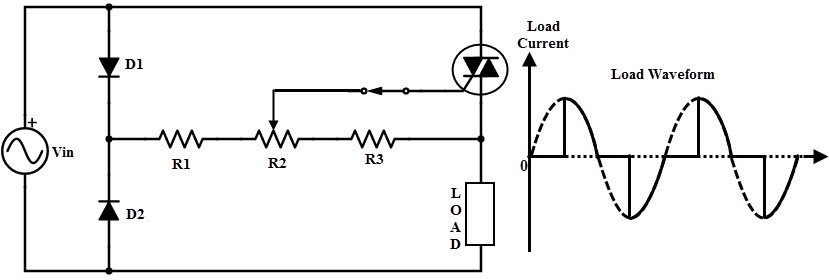
As soon as the input AC supply is given to the circuit, triac is in blocking state (either forward or reverse) provided that the applied voltage is less than the VBO or gate current is less than the minimum gate current. During the positive half cycle of the input, diode D1 is forward biased and hence a positive gate current is applied to the gate.
Therefore, the gate is triggered thereby triac comes into the conduction state. During the negative half cycle of the input, diode D2 is forward biased, hence the gate current flows through it thereby triac is turned ON.
Likewise, AC power delivered to the load is controlled in either direction by applying a proper gate signal. The conduction angle of the triac is controlled by varying the resistance R2 in the above circuit.
Triac Vs SCR
- Triac is a bidirectional device, whereas SCR is a unidirectional device.
- Triac terminals are MT2, MT1 and gate whilst SCR has anode, cathode and gate terminals.
- For both positive and negative gate currents, traic conducts but with only direction on gate current turn ON the SCR.
- Four different modes of operation are possible with triac, whereas with SCR one mode of operation is possible.
- Triac are available in less ratings compared with SCRs.
- Triac characteristics are laying in first and third quadrants while SCR characteristics lay in the first quadrant.
- Reliability is less compared with SCRs.

One Response
can u throw some more light in mode4 operation of triac. how p1n1 junction started to conduct and the regenerative action.