This article introduces resistors, essential components in electronic circuits, emphasizing their role in managing current flow and energy conversion, such as in light bulbs. It explores different resistor symbols, their necessity for regulating current to prevent component damage, and the factors influencing resistor choice, including capacitance value and working voltage.
What is Resistor?
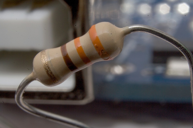
Resistor is basic component that is used in all the electronic circuits. It is a passive element that resists the flow of electrons. Thus it allows only certain amount of current to pass through it. Remaining current is converted into heat.
The working principle of bulb is that electricity is passed through the filament usually tungsten, which is a resistor. The energy is converted to and released as light and heat.
Resistor Symbols
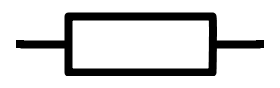
Generally there are two standards that are used to denote the symbol of a resistor viz.Institute of Electrical and Electronics Engineers (IEEE) and International Electro Technical Commissions (IEC).
The IEEE symbol of resistor is a zigzag line as shown in the below figure.

The IEC symbol
Why is a resistor used in a circuit?
Let us take an example to answer this question.
- Consider an LED connected to a battery of 9V. Assume the Forward current of the LED is 3mA.
- If a resistor is connected between the Led and battery the Led will glow.
- If there is no resistor in between LED and battery , Led will glow but after some time it heats up enormously. This is because of the more current(>30 mA) Passing through the LED.
- Thus Resistor is necessary to control the current flow.
- Resistor used in the circuit can be used for many purposes. For example to adjust the voltage levels, to provide biasing to active components, for dividing the voltage levels etc.
What is a resistor made out of ?
- Resistors are made of ceramic rods coated with a metal or metal oxides.
- This coating determines the resistance value of the resistor.
- If coating is thicker, lower is the resistance value of the resistor.
What is Resistance?
- Resistance is the property of the resistor to oppose the current. Let us understand this clearly.
- Generally materials are divided as conductors and insulators.
- Conductors allows the current to flow through them as they have free electrons.
- Insulators do not have electrons and they oppose the free movement of electrons in them. This opposing force is resistance.
- Different types of resistors are made with different compositions.
Thus resistance can be defined as the opposition force offered by the material to the current flow.
How do You calculate Resistance?
The mechanism of energy flow through a conductor can be described as follows
In the presence of an active source, the passive elements like resistors will always absorb energy and the currents through them will always flow from higher potential to lower potential.
If the same potential difference is applied between the ends of two different but geometrically similar conductors like rods of copper and of glass, it results in different currents. This characteristic of the conductor that results in different currents is its electrical resistance.
The definition of resistance can be derived from the Ohm’s law in its Electromagnetic theory form or Continuum form
J = σ E —-1
Here σ is the conductivity of the material i.e. conductor.
E is the electric field developed along the length of conductor due to flow of electrical energy through the conductor.
If ‘V’ is the voltage drop across the conductor and ‘L’ is the physical length of conductor then
E = V/L —-2
The current density J is resulted within the conductor due to the flow of electrical energy through the conductor.
If ‘I’ is the current flowing through the conductor and ‘A’ is the cross sectional area of conductor, then by the definition of current density
J = I/A —-3
Now combining equations 1, 2 and 3
I/A = σ V/L
V = (L/Aσ) I —-4
The term in parenthesis is constant and let us denotes it by ‘R’.
∴V = R I
This is the Ohm’s law form in circuit analysis.
By the definition of Ohm’s law, the current flowing through a conductor is directly proportional to the potential difference applied.
I ∝ V
The proportional constant is called Resistance parameter of the conductor R.
∴I = V/R
R = V/I
The resistance of a conductor, between its two points is determined, by applying a potential difference V between those two points and measuring the current I .
The unit of resistance is Volts per Ampere and is given the name Ohm (Ω).
∴ 1Ω = 1 volt per ampere = 1 V/A.
From earlier calculations
V = (L/Aσ) I
∴ R = L/(A σ) I
σ is the conductivity of the conductor which is the measure of conductor’s ability to conduct electric current.
1/σ is the reciprocal of electrical conductivity called electrical resistivity denoted by the symbol ρ (rho).
Resistivity is the measure of a conductor’s ability to resist the flow of electric current.
∴ Resistance of a material ∝ resistivity of the material.
R = ρL/A Ω
Resistance of a conductor can be defined as the conductor’s opposition to the flow of current through it.
Resistance is a property of an object like conductor. Resistivity is a property of a material from which the object is made.
Resistance value of a given resistor can be read from the resistor color code given on it.
What is the Power rating of a Resistor?
Power rating of a resistor is the maximum value of power (combination of voltage and current) a resistor can handle.If the input power of the resistor is greater than this value, resistor may damage.Power rating of a resistor is also called wattage.
Resistors have wide range of power ratings from 1/8th to 1 watt.Resistors with more than 1 watt are called Power resistors.
V-I Characteristics of a Resistor
V-I Characteristics of a resistor are the relation between the applied voltages and the current flowing through it.
From Ohm’s law, we know that when the voltage applied across the resistor increases, the current flowing through it also increases i.e. the voltage applied is directly proportional to current.
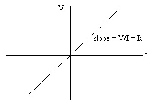 The above specifications are valid in case of a pure resistance i.e. ideal resistor and the temperature is constant.
In practical conditions, these values may vary depending on the operating environment and the characteristics might be different from the ideal linear values.
Variation of Resistance with Temperature
- As the temperature of the surroundings increases the resistance of the material changes.
- The reason for this change is not because of the variations in the dimensions of the material but rather the change in the resistivity of the material.
- When there is a rise in the temperature, the heat will cause an atomic vibration and these vibrations will cause a collision between the free electrons and the electrons in the inner layers of the atom.
- These collisions will use the energy of free electrons. If more collisions take place, more energy of free electron is used and increases the resistance to flow of current. This is the case in conductors.
- In case of insulators the resistance decreases with increase in temperature.
- The reason is the availability of number of free electrons which are released from its captive stage.
- In mathematical terms, a fractional change in resistance is directly proportional to the change in the temperature.
In mathematical terms, a fractional change in resistance is directly proportional to the change in the temperature.
∆R/R0∝∆T
Where ∆R is the small change in resistance
∆R = R – R0
R is resistance at temperature T
R0 is resistance at temperature T0
∆T is change in temperature
∆T = T – T0
If we denote the proportionality constant in the above equation as alpha (α)
Then ∆R/R0 = α∆T
Where α is the temperature coefficient of the resistance.
The temperature coefficient of resistance is used to describe the relative change in resistance in association with change in temperature.
If the change in temperature is small then the above equation can be written as
R = R0 [1+α (T-T0)]
If the resistance increases with increase in temperature, then the material is said to be having a positive temperature coefficient. These materials are conductors.
If the resistance decreases with increase in temperature, then the material is said to be having a negative temperature coefficient. These materials are insulators.

7 Responses
I like it it is good for me
Thanks for it! I understand a lot in this.
This is really a great informative blog about “Resistors”. It might be small in size but plays a major role in the electronics product.
I love you website and as a wanna be electronics engineer, I can always find answers to my questions in a way that I’d understand it. Thanks for all the good work.
Thanks for all the good work
Thanks for the website. I find it helpful to some of my questions about resistor.
Nice Information about resistors. Thank you.