Emerging technologies are making our life simpler these days. With the introduction of mobile phones, life has changed rapidly. This is a dream of radio engineering. Mobile phones merged land line telephone systems. These days, many advancements in the mobile phones were introduced.
These advancements provide many services such as text, internet etc. But although there are many advancements in the technology, we still rely on the wired battery chargers. Each phone will have its own designed battery charger. Thus the battery chargers are required to carry everywhere to keep the battery backup. Now just think of a battery charger that charges your mobile automatically. When you sit for tea and place your mobile on the table, it simply charges your mobile. This article explains a simple wireless battery charger circuit that charges your mobile when placed near the transmitter. This circuit may be used as wireless power transfer circuit, wireless mobile charger circuit, wireless battery charger circuit, etc.
Also get an idea about How to Design a USB Mobile Charger Circuit?
Wireless Battery Charger Circuit Principle:
This circuit mainly works on the principle of mutual inductance. Power is transferred from transmitter to the receiver wirelessly based on the principle of “inductive coupling”.
Inductance is the property of the conductor, in which the current flowing in a conductor induces a voltage or electromotive force in it or in another nearby conductor. There are two types inductance. 1) Self inductance, 2)Mutual Inductance.
“Mutual inductance” is the phenomena in which, when a current carrying conductor is placed near another conductor voltage is induced in that conductor. This is because, as the current is flowing in the conductor, a magnetic flux is induced in it. This induced magnetic flux links with another conductor and this flux induces voltage in the second conductor. Thus two conductors are said to be inductively coupled.
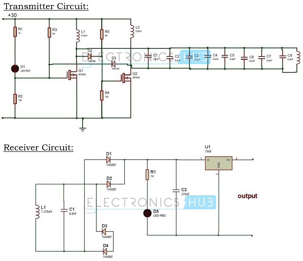
Wireless Power Transfer Circuit Diagram:
Wireless Mobile Charger Circuit Design:
Wireless battery charger circuit design is very simple and easy. These circuits require only resistors, capacitors, diodes, Voltage regulator, copper coils and Transformer.
In our Wireless battery charger, we use two circuits. The first circuit is transmitter circuit used to produce voltage wirelessly. The transmitter circuit consists of DC source, oscillator circuit and a transmitter coil. oscillator circuit consists of two n channel MOSFETS IRF 540 , 4148 diodes. When the DC power is given to the oscillator, current starts flowing through the two coils L1, L2 and drain terminal of the transistor. At the same time some voltage is appeared at the gate terminals of the transistors. One of the transistors is in on state while the other is in off state. Thus voltage at drain of transistor which is in off state raises and it fall through the tank circuit made of 6.8nf capacitors and transmitter coil of 0.674. Thus operating frequency is determined by using formula F=1/[2π√(LC)].
In the second circuit that is receiver circuit consists of receiver coil, rectifier circuit and regulator. When the receiver coil is placed at a distance near the inductor Ac power is induced in the coil. This is rectified by the rectifier circuit and is regulated to DC 5v using 7805 regulator. The rectifier circuit consists of 1n4007 diode and capacitor of 6.8nf. The output of regulator is connected to the battery.
NOTE: Also get an idea about the Battery Level Indicator Project Circuit and its Working
How to operate this Wireless Power Transfer Circuit?
- Initially, connect the circuit as shown in the circuit diagram.
- Switch on the supply.
- Connect the battery charger at the output of the circuit.
- Place the receiver coil near the transmitter coil .
- You can observe the charging of battery.
Wireless Battery Charger Circuit Advantages:
- Usage of separate charger is eliminated.
- Phone can be charged anywhere and anytime.
- It does not require wire for charging.
- Easier than plug into power cable.
Wireless Power Transfer Circuit Applications:
- Wireless chargers can be used to charge mobiles, camera batteries, Bluetooth headsets etc.
- This can also be used in applications like car battery charger with little modification. Go to Simple Car Battery Charger Circuit post for more information.
- This can also be used in medical devices.
Limitations of the Circuit:
- Power is somewhat wasted due to mutual induction.
- It will work for very short distances only. If you want to use it for long distances, then the number of inductor turns should be high.
[Also Read:Adjustable timer Circuit With Relay Output]

131 Responses
finally connecting to the charger ,either it is a charger or the battery,will you expand it
Connect the output terminals to charging pin, so that you can charge your mobile.
Does the turns of copper wire affect the o/p of the circuit?? If so what is the ratio of o/p and turns of copper wire
Yeah,it matters.
pls mention all the component with their value
i am doing it in my clg
pls help me out
what is value of tank circuit inductor?
The value of tank circuit inductor is 0.674 micro henry
what is value of R3 and R5 ????
94 ohm
why connected for 230v current in LED driver circuit?
super
useful website for garib log
what are the component weare use?
all components mentioned above
What is the value of capacitor and resistor in ossilating circuit
It would be very good if you please mention the values of R,L and C.
Send the capacitance and resistance values in the oscillator circuit.
How can I get help to build the Oscillator Circuit ?
how to generate 10mhz frequency for this circuit.
Hey!
Please can your give me formula for to get value of resistor 1,2,3 & capacitor 3,4,5.
Please help me.
can we use rc phase shift oscillator in this circuit
I like to make this for my collage project. Can anyone give me the component list?
which values.capacitors or ressistor i can use.
.for c3 c4 c5…or R1 R2 R3
How can I make 1mh coil? Is there should be same size in master and slave coil? If not then how many round have to give?
Please help me.
How can I make 1mh coil? Is there should be same size in master and slave coil? If not then how many round have to give?
PLEASE HELP ME WITH DESIGN OF THE OSCILLATOR CIRCUIT FOR GENERATING 10MHZ FREQUENCY
can you give the values of resistors and capacitors used in oscillator circuit
how to design oscillator circuit and select the capacitor & inductor values
Very useful site for Engineering Students
there is a Rectifier circuit.i think it was full wave rectifier but there is a no center tapping to the transformer and my doubt is the circuit given above is working or not.If it is correct then could you please send me the list of componets along with their values
plz tell me the exact value of resistors and capacitors of the oscillator circuit..plzz reply asap..
How to determine the capacitor and inductor values for the ocscillatory circuit
I did it all but even set the values of capacitor and resistor in oscillator ckt.
in transmitter ckt, the output after v reg is as required 12 V but the output of osc circuit is 0
sir is this ckt is like power bank …….
very useful for all engg. students those who want to really learn something………..
i know more about renewable and non renewable resources…………….please help me….
Will you please send all the values of resistors and capacitors.
This circuit is complete rubbish, unfortunately. It will not do anything useful at all. – Russell McMahon
yeah, the “oscillator” is connect via a single wire, that will surely work… together with the two diodes pointing in the same direction this will be a brilliant device to show how not to do things
How to calculate the resistor and capacitor values (c3, C4, C5, C6, R3, R1, R2) in wireless power transfer circuit
why we use 1N4007 diode twice as it is not even act as full wave rectifier
Sir, will you please send all the values of components. It is much needed.
This circuit is not correct and will not work. It is incredibly irresponsible to post circuits like this, particularly that include a mains input. How about you review circuits before posting them?
SIR, would you please send the values of all the components.
how will we get inductor coil..
input is ac 230v will u not explain it …
Convert input AC to 30v DC using LM317 voltage regulator and pot.
If I would like to use LM317 I will replace with IRF540?
I have done this project yesterday. The circuit is well working. Thanks for sharing.
i done this project. but not working. my first mosfet getting heated. i dont know how many turns of transmitter reciever. and also diameter and length of transmitter and receiver. please help me
Please told me about the coil turn and resistors value.
Brother i also want to make itt as my project,If you show me complete circuit with pareter values as well as inductor turns and wire gauge it will be helpful for me.Please share.
Why we are need oscillator in that circuit no oscillator in block digram every done this project please give your mobile number
what is the value of resistor R3 and R5 in trasistor circuit?
And how many turns we have to take for transistor and resistor to work properly???
Hello can u help me
you mentioned to connect the output terminals to the charging pin , charging pin of what ????
sir, i am a student who is willing to do this project with complete idea of it’s operation as well as design… so can you please give the design equations or the design procedure to get the resistor , capacitor and inductance values sir… it will be very much helpful for me sir… so please provide the requested information sir…
thanking you..
it possible its range in 1 m ?
It may not be possible up to the range of 1 m.
how much turns of coil we should take for each inductor?
what os the value of inductor in front of capacitor c8
Hi,
I want to design LED lights for my home when there is no power.Can you tell me the circuit diagram with material details.
Secondly is there any led lights for home with the help of magnatic genrator.
Thanks
Narendra
how can I make that coil ?
is it a self made coil?
please answer
i have done the circuit connections yesterday and iam changed the value of inductors- 8.6uh as 10uh and 0.674uh as1uh and in the receiver circuit 1.235uh as 3uh. i give the power supply one of the mosfet is burst. please explain it.
hello sir …………..
i want to buy wireless mobile charger
how to buys this project pls tell me
my contact no. 8923701540
hello sir
i want to buy wireless mobile charger project
give me some more information about this project
my co. 8923701540 plsssssssssss help me
what is the value of L1 nd r3??
how to increase the distance between tx & rX..pls explain..i want to extend it to 5meters
i am going to do exactly this project on my final year but i have a qn regarding the last six capacitors.
Is it a must to put them in series as many as they are or i can just add them and put a one capacitor with total capacitance.?
Same question please answer…..in my email
parthkadiya772@gmail.com
For the Red LED in the circuit, is that an LED driver or just a regular LED? I am trying to do a SPICE simulation for this.
how can i get the30v supply
what is the maximum range
what is the value of L1,L2 and R5????
what distance it covers? means how much the maximum distance we will get from this circuit?
Hi admiin,
i want to make this circuit but i am not sure to make the transmitter coil with 0.674uH and inner diameter is 30mm. how must i turns?
I also did not find inductor with 8.6uH values in my town. It can be change with any others, 10uH maybe?
can please elaborate that what is the output voltage of receiver circuit
isn’t working any few meters?.
Can someone please help me urgently. I’ve been trying to do this project for a month now but whenever I test the transmitting circuit it is giving me short circuit.
i have one question what is the input voltage of the transmitter circuit
If i use 24 volts ac in input, integrated 683pf capacitor this circuit will work?How turns and what gauge of inductor wire?please reply me because its my project.
Connect the battery charger at the output of the circuit What that mean. and what type of Battery charger used.
Connect the battery charger at the output of the circuit what that mean and what type of battery charger used please explain how we can get the output?
What is the name of the induction coil in proteus soft ware (every done this circuit please give ur mobile number to me please)
what is the operating range of this wireless charger.and the give values of componenets used in the ciruit.
Range depends on the number of turns and diameter of the coil.
which value of resistors and capacitors have to use????
You can find the values of capacitors and resistors in the circuit diagram
How do you calculate the values of each component in this circuit
how much ampere are use in the dc power supply of the circuit
Can you please elaborate the “How to operate this Wireless Power Transfer Circuit?” part.
How to use once the circuit is done?
if we given power supply 0f 12v dc to my circuit with a change inductor values 10microh and tanker circuit with 1 microh my ir 540 mosfet get burned help us to find our output
What is the valus of coils and in Tx ckt which is the coil..?
what will be the input of transmitter ckt and how?.. and also what should be turns of both the coils ..am also tried this ckt in multisim but its not working …help me pls
how many turns needed for transmitter coil and how many turns needed for receiver coil and pls give a oscilator circuit with all values……pls soon
well said i am with you 🙂
i how your project.your project is so good. actually i want to make the wire bettery charger can you help me step by step meke it
What is the size of resistor #5?
hello! I’d like to watch a video about the circuit, I want to see how to “build it”
how to calculate the value of inductor and other components, if the distance between transmitter and receiver has to increase
is this possible to construct this circuit for more than one receiver
what is the use of red led’s here
I want video how to implement this ckt. can u plz send dat to my email ID
I make this circuit but it not working so plz send
How to make this project circuit plz send video in my email id…
How to make 6.8 uh inductor wht is the length of coil and width and wire guage plzz reply
I built this circuit and had to calculate the component values to oscillate around 100KHz for best results. Interesting concept. Original charger takes approx. 1 hour. This one takes 2 hours to fully charge from fully depleted state. Thanks for a great idea! .Also you have an omission mistake in your receiver diagram – D3/D4 anodes must be connected to output negative, otherwise there will be no current flow and C2 will not charge!!
Good catch Fred. I am an electrical engineering master’s student and am thinking about building this circuit for fun.
That’s how you dummy proof circuits. Add a little mistake so that you are forced to understand what you are doing!
Fred (or anyone who has implemented the circuit) kindly send me the component values that you used to implement the 100KHz circuit. Also, what did you use to protect the mosfets from blowing up?
what is the distance of the transmitter and receiver coil in order to charge ? and what is the diameter of the wire used and the number of turns.?
Sir how to make 6.8 uh inductor whats its length and width and wire guage plzz reply very important
please send mi all the values required for this project
the out put voltage is 5v and how much is output current ?
sir can please give me the value of the components used in it the values in the diagram is not clear enough. Also mention, how the circuit work i decide to do this as my project please help me
what are the disadvantages of this circuit
Admin!u must should mention the input source how is it connected or used and the main thing is turns of coils and their gauge.i can’t find where is coil used or inductor ….Regardz
what is the value of R3 and R5 since it is not clearly visible.
can you please send me a video of that project and also if i used 4.7 uF does it will work
PLEASE CAN YOU USING WORDS INTEAD OF LEABLING SYMBOL?
how to connect battery to the circuit
can you pls post any video of working of this wireless power transmitter.
can you give the specification of all components.What can be used as DC source
how much dc supply we have to give in this circuit
i have the same question i think its 30volt as written on the image but im not sure
Where we connect transformer? Or where is the transformer in the ckt?
what is price of thise project,,,,,,, information about project ,advantage , usese .
Can anyone tell me the estimation of the cost required for this project
Anyone who has done this project, how are you protecting the mosfets from burning up?
What is coil size??(both)
Will I be able to reduce the wastage of power due to mutual induction ?
If yes , give me the solution for it..
how much range this work please answer me fast ..and kindly send me all documents related to this project…
send me all documents via mail plz..
i made this circuit on Proteus but it does’t transmit current from sender to receiver circuit,what’s the issue?
i am waiting for your fast reply.