The phase rotation or phase sequence measurement is needed when connecting three phase supplies to electrical drives, electrical motors and other electrical systems.
Phase sequence meters show the correctness of three phase connection to loads. If the phase sequence is not in a correct manner, it will lead to malfunction of load systems. Let us look at this concept in brief.

Outline
ToggleConcept of Phase Sequence
The order in which the individual phase voltages attain their respective maximum values in a three phase system is called phase sequence. Let us see how this happens with following discussion.
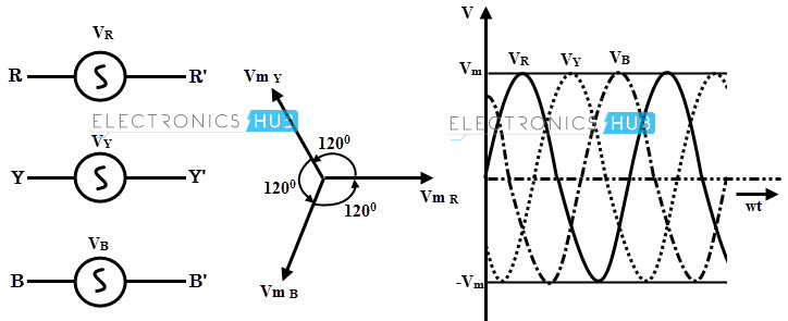
A three-phase supply system needs three single phase EMFs provided they must have same voltage magnitude and frequency but with different phase displacement, usually by 120 degrees.
The three single phase emf sources and their phase relationship is shown in figures a and b. Here the length of each phasor indicates peak or maximum value of each emf.
These phasors are assumed to be rotating in positive or counterclockwise direction at an angular frequency, w. The timing diagram for these phasors is shown in figure c and it is obtained by projecting each of these phasor onto the vertical line.
As phasors rotate in a counterclockwise direction, the positive maximum value first occurs for phase R, and then a succession for phases Y and B.
Therefore, the phase Y lags phase R by 120 degrees which is one third of the cycle and phase B lags phase Y by 120 degrees. For this reason three phase supply system has a phase phase order of RYB. This phase order is also termed as phase rotation and phase sequence.
This phase sequence is essential in many three-phase applications for an appropriate operation by the loads such as three phase motors. The instantaneous voltages of three phase system for each phase voltage are given as
VR = Vm sin wt
VY = Vm (sin wt – 120)
VB = Vm (sin wt – 240) or Vm (sin wt + 120)
The phase sequence of a three phase supply system can be changed by interchanging connections of any two phases.
Correct Phase Sequence Needed?
The phase sequence of source voltages is essential in three-phase supply systems in many industrial applications. If the phase sequence is incorrect, it will lead to malfunctioning of equipments also cause serious damage to the load.
In case of lighting and heating applications, the phase sequence is not important, but for loads like motor drives, it must be considered.
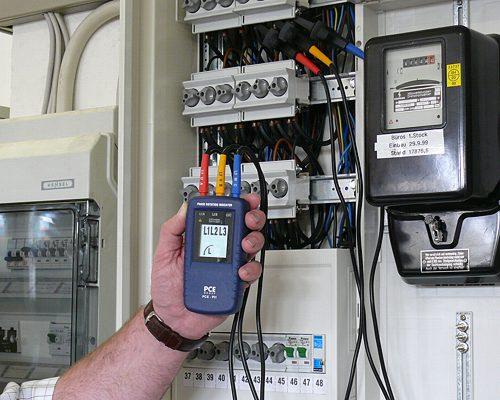
- In case of three-phase induction motor, reversal of phase sequence will result reversal of its direction. So the correct knowledge of phase sequence is required before applying three phase voltage to the motor, otherwise the loads connected to the motor considerably get affected.
- For unbalanced three-phase systems, a reversal phase sequence will cause certain branch currents to change its magnitude. In such conditions, the system will give completely different values of currents and voltages.
- In parallel operation of transformers and also alternators, making sure of correct phase sequence is very essential. The reversal of phase sequence of any one machine can cause serious damage to the entire system.
[Read: Synchronization of Alternators]
Phase Sequence Meters or Indicators and Their Types
The phase sequence can be determined in several ways, such as oscilloscope and two lamps-one capacitor methods. However, such methods are basic checking methods.
The most widely used method of checking phase sequence carried by a phase sequence meter.
A phase sequence meter or indicator can be a wall or panel mount or handheld instrument which determines the phase sequence of three phase supply systems. The display of these meters indicates the order of phase sequence to which their terminals are designed.
There are different types of phase sequence meters available depending on various factors like different voltage ratings, type of indication, solid state type or electromechanical, etc.
There are two basic phase sequence indicators, namely
- Rotating type
- Static type
Rotating Type Phase Sequence Indicator
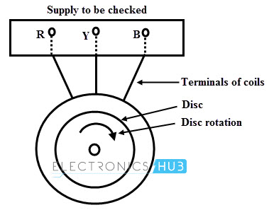
The principle of working of this type of motor is same as that of three-phase induction motor. It consists of three stationary coils which are separated from each other by 120 degrees in space. These are connected in star fashion and the ends are brought out for the connection.
These three ends are connected to the three-phase supply where the phase sequence is to be checked. A disc is mounted on the top of these coils, and its direction of rotation decides the phase sequence.
When these star connected coils are excited by a three-phase supply, a three phase rotating type of magnetic field is produced where each coil alternating flux is separated from each other by 120 degrees in space as similar to the three-phase induction motor.
As this rotating flux passes over the disc, emf is induced in the stationary disc. The eddy current induced by this emf interact with rotating field and develops a torque in the disc and hence it starts rotating.
Since the direction of rotating magnetic field depends on the phase sequence of the supply and thus the rotation of the disc. The disc is marked for particular direction for correct phase sequence.
If the supply is given to the terminals, disc rotates in that direction, then it is said to be correct phase sequence. If the disc rotates in opposite direction, it indicates opposite phase sequence of the supply.
Static Type Phase Sequence Indicator
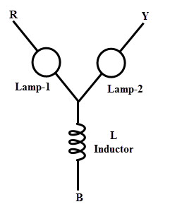
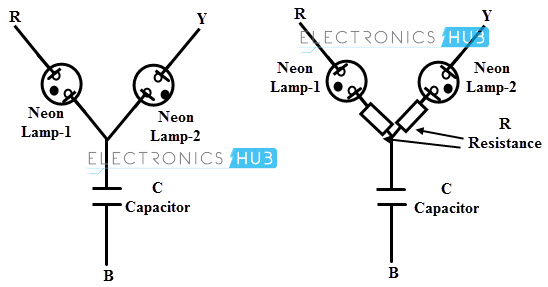
In this type, few arrangements of lamps with inductor or capacitor are used for indicating the phase sequence. The proportional brightness and darkness of lamps decide the phase sequence of the three-phase supply. The following are two arrangements of a static type phase sequence meter.
In one arrangement, two lamps and an inductor are connected such that two phases (R and Y) consist of lamps as loads and other phase has inductor as a load in B phase shown in figure.
In this case, the lamp-1 glows dimmer while lamp-2 glows brighter for a phase sequence of R-Y-B. In case of phase sequence R-B-Y, the lamp-1 glows brighter while lamp-1 glows dimmer. From these two cases of lamps, phase sequence is determined.
In another arrangement, normal lamps are replaced with neon lamps and instead an inductor, a capacitor of value XL =XC is used.
It is to be noted that when voltage is less than the breakdown voltage of the neon lamp, then it doesn’t glow. This property of neon lamps avoids the confusion of bright and dim conditions of previous normal type indicator.
The phase sequence is said to be R-Y-B when lamp-1 glows bright while lamp-2 doesn’t glow and remain in dark.
If lamp-1 remain dark while lamp-2 glows bright, then it is a phase sequence if R-B-Y. In practice, neon lamps are connected in series with resistors in order to limit the current.
Solid State Phase Sequence Meter
This type of phase sequence meter use solid state electronic components to build a phase checker circuit. It may consist of LEDs to show clockwise and counter clockwise phase rotation.
You can access a simple circuit using NAND gates for a phase sequence checker .
[Read : Phase Sequence Checker]

Some electronic circuits may use zero crossing detection circuits for finding the phase displacement or phase rotation of three phases.
This zero crossing detection circuit enables the checking of R-Y-B and R-B-Y sequences and correspondingly gives LED indication.
In many such circuits, microcontroller units are used so that additional parameters can also be displayed such as power factor.
Image Credits
- Phase sequence Meter : test-meter.co.uk
- Phase Rotation Meter : industrial-needs.com
- Solid State Phase Sequence Meter : happyhew.com


2 Responses
I came across your website site on google and verify some
of your early posts. Continue to keep up the good function.
I recently extra up your rss. Seeking forward to reading more from you later on!
Very informative