In this tutorial, we will learn what is an Open Circuit Test and Short Circuit Test in the context of Transformers, how to perform Open Circuit and Short Circuit Test on Transformer, calculate the efficiency of these open circuit and short tests and also calculate the regulation.
Overview of Open Circuit and Short Circuit Test
It is possible to predict the performance of a transformer at various levels of load by knowing all the equivalent circuit parameters. These circuit parameters are supplied in terms Open Circuit (OC) and Short Circuit (SC) test data of a transformer. Without actually loading the transformer, these two assessed tests give the test results, which are used to determine the equivalent circuit parameters.
By these parameters, we can easily predetermine the efficiency and regulation of the transformer at any power factor condition as well as at any load condition. This method of finding the parameters of a transformer is called as an Indirect Loading Method.
This tutorial enumerates how to perform these tests, how determine the equivalent parameters from test data and significance HV or LV side in which the calculation to be performed.
Open Circuit or No Load Test on Transformer
This test is performed to find out the shunt or no load branch parameters of equivalent circuit of a transformer. This test results the iron losses and no load current values, thereby we can determine the no load branch parameters with simple calculations.
As the name itself indicates, secondary side load terminals of the transformer are kept open and the input voltage is applied on the primary side. Since this test is carried out without placing any load, this test is also named as No Load Test.
How to Perform Open Circuit Test?
The open circuit (OC) test is carried out by connecting LV side (as primary) of the transformer to the AC supply through variac, ammeter, voltmeter and wattmeter instruments. The secondary side or HV side terminals are left open and in some cases a voltmeter is connected across it to measure the secondary voltage.
The primary side voltmeter reads the applied voltage to the transformer, ammeter reads the no load current, wattmeter gives the input power and the variac used to vary the voltage applied to transformer so that rated voltage is applied at rated frequency. The OC test arrangement of a transformer is shown in below figure:
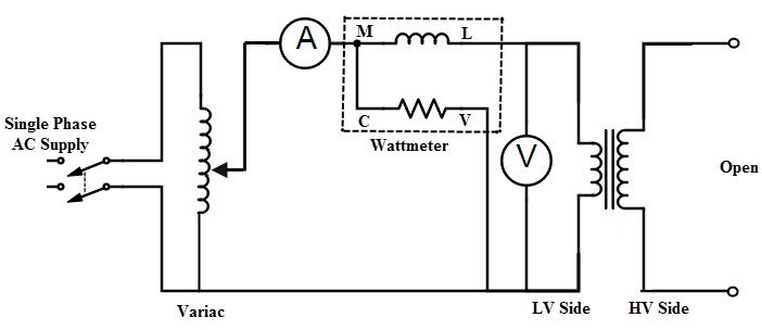
When a single phase supply is given to the transformer, the rated value of the primary voltage is adjusted by varying the variac. At this rated voltage, the ammeter and wattmeter readings are to be taken. From this test, we get rated voltage VO, input or no load current IO and input power WO.
We know that, when the transformer is on no load, the no load current or primary current is very small, typically 3 to 5 percent of the rated current value. Thus, the copper loss in the primary winding is negligible.
In OC test, transformer is operated at rated voltage at rated frequency so the maximum loses will be the flux in the core. Since the iron or core losses are at rated voltage, the power input is drawn to supply the iron losses by the transformer under no load.
WO = Iron losses
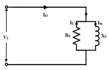
The no load shunt parameters are calculated from the OC test as
The no load power factor, Cos ΦO = WO/VOIO
Once the power factor is obtained, the no load component currents are determined as:
Magnetizing component of no load current, Im = IO sin ΦO
Core loss component of no load current, Im = IO cos ΦO
Then, the magnetizing branch reactance, XO= VO / Im
Resistance representing core loss, RO = VO / IO
When the transformer is operating on no load, the current drawn by the shunt or parallel parameters is very small, about 2 to 5 percent of the rated current. Thus, a low current will flow through the circuit during OC test. In order to be readable by the instruments, the measurements of voltage, current and power must be performed in the low voltage side.
And also, low range current coils and low range ammeter must be selected. The power factor of the transformer on no load is too low. which is typically below 0.5 . So, in order work with this low value, a LPF watt meter is selected. The equivalent circuit obtained by the OC test is shown below:
Short Circuit Test on Transformer
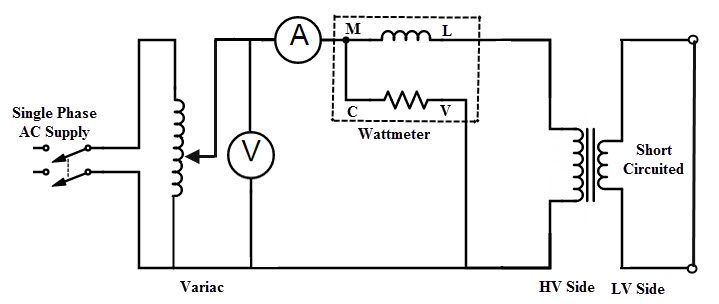
This test is performed to find series branch parameters of an equivalent circuit such as equivalent impedance (Zo1 or Zo2), total winding resistance (Ro1 or Ro2) and total leakage reactance (Xo1 or Xo2). Also, it is possible to determine copper losses at any desired load and total voltage drop of the transformer referred to primary or secondary. In this test, usually LV winding is shorted by a thick wire. And the test is conducted on the other side, i.e. HV side (as primary).
How to Perform Short Circuit Test?
In Short Circuit (SC) test, the primary or HV winding is connected to the AC supply source through voltmeter, ammeter, wattmeter and a variac as shown in figure. This test is also called as Reduced Voltage Test or Low Voltage Test. As the secondary winding is short circuited, at rated voltage, the transformer draws a very large current due to its very small winding resistance.
Such high current can cause overheating and also burning of the transformer. Thus, to limit the high current, the primary winding must be energized with a low voltage, which is just enough to produce the rated current in the primary of the transformer.
The SC test is conducted on HV side due to the two main reasons. The first one is, the SC test conducted by applying rated current and the rated current of the HV side is much less than that of the LV side. Therefore, the rated current is easily achieved at HV side (due to the low current value) as compared to the LV side.
On the other hand, if we short the HV terminals by connecting measuring instrument on LV side, voltage in the secondary is zero. Therefore, the current flow through HV side is very high (as VA rating is constant) compared to the LV side and hence it will cause to burn the transformer.
During this test, by varying the variac slowly, we apply a low voltage to the primary typically 5 to 10 percent of the rated voltage to cause a rated current to flow in both primary and secondary windings that we can observe on ammeter reading (in some cases, the secondary is shorted through an ammeter). At this rated current, we have to record the voltmeter (Vsc), ammeter (Isc) and wattmeter (Wsc) readings.
In this test, the current flow is rated value and hence no load current is very small and is 3 to 5% of the rated current. In other words, the voltage applied to the primary winding is very low, thereby the flux level in the core is very small. In turn there is negligible core loss. Therefore, the no load shunt branch is considered as absent in equivalent circuit of this test as core loss is negligible.
As the iron or core losses are function of voltage, these losses are very small. Therefore, the wattmeter reading shows the power loss or I2 R loss equal to the full load copper losses of the whole transformer.
Wsc = Full load copper losses
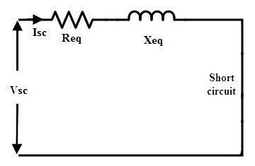
Form the test results we determine the series branch parameters of an equivalent circuit as
Equivalent resistance referred to HV side, R01 = Wsc/ Isc2
Equivalent impedance referred to HV side, Z01 = Vsc / Isc
Equivalent leakage reactance referred to HV side, X01 = √ (Z201 – R201)
And also short circuit power factor, Cos Φsc = Wsc/VscIsc
The equivalent circuit obtained from this test is shown below.
It should be noted that, before calculation of parameters, you must be aware in which side (primary or secondary) the test reading being recorded. Suppose if the transformer is step-up transformer, then we carry out the SC test on secondary side (HV side) while primary or low voltage side is shorted. In such case, we get the parameters referred to the secondary from calculations such as R02, X02 and Z02.
If it is a step-down transformer, we get the parameter values as R01, X01 and Z01 because the meters are connected to the HV side of the primary.
From the OC test we get, shunt branch parameters referred to the LV side and from SC test we get series branch parameters referred to HV side. Therefore, for a meaningful equivalent circuit, all the parameters must be referred to the one particular side. The explanation regarding this transformation is explained in equivalent circuit of the transformer topic in our earlier articles.
Calculation of Efficiency from O.C. and S.C. Tests
As we have seen that, the practical transformer has two types of major losses namely copper and core losses. The temperature of the transformer rises due to these losses which are dissipated as heat. Due to these losses, input power drawn by the primary no longer equal to the output delivered at secondary. Therefore, the efficiency of the transformer is given as
Efficiency, η = Power output in KW/ Power input in KW
= Power output in KW/ (Power output in KW + Losses)
= Power output in KW/ (Power output in KW + Copper loss + Core loss)
We have discussed that, the core loss Pcore remains constant from no load to full load as the flux in the core remains constant. And the copper losses are depend on the square of the current. As the winding current varies from no load to full load, copper losses are also get varied.
Consider that the KVA rating of the transformer is S, a fraction of the load is x and the power factor of the load is Cos Φ. Then
The output power in KW = xSCos Φ
Suppose the copper loss at full load is Pcu (since x =1),
Then copper loss at x per unit loading = x2Pcu
Therefore the efficiency of the transformer is
Efficiency, η = xSCos Φ / (xS Cos Φ + x2 Pxcu + Pxcore)
In the above efficiency equation, the core or iron losses and full load copper losses are found by OC and SC tests.
Calculation of Regulation
For a fixed voltage in the primary, the secondary terminal voltage will not be maintained constant from no load to full load. This is due to the voltage drop across leakage impedance which magnitude depends on both degree of loading and the power factor.
So the regulation gives change in secondary voltage from no load to full load at a given power factor. It is defined as the change in the secondary voltage when the transformer is operating at full load of specified power factor supplied at rated voltage to no load with primary voltage held constant.
Percentage voltage regulation, %R = ((E2 – V2)/ V2 )×100
The expression of voltage regulation in terms voltage drops is given as
%R = ((I1R01 cos Φ +/- I1X01 sin Φ) / V1) ×100
Or
%R = ((I2R02 cos Φ +/- I2X02 sin Φ) / V2) ×100
The above two equations are used based on the parameters are referred to primary or secondary sides. Hence, from the SC test data we can find out the regulation of a transformer. The positive sign is used for lagging power factor and negative sign is used for leading power factor.
Conclusion
A beginner’s guide on Open Circuit and Short Circuit Test of a Transformer. You learned how to perform Open Circuit and Short Circuit Test on Transformer, calculate the equivalent circuit parameters, calculate the efficiency and percent of regulation.

5 Responses
It is very helpful article for me so thank you very much.??
Very useful article. The open-circuit power is the voltage difference measured between two terminals when no current is supplied. The short circuit current is the current that flows when the stations are forced to have zero voltage change.
This is a good article on Transformer tests.
the explanatoin was ok .only that i expected better elaborations through some worked examples
It was very explanation. Thank you.