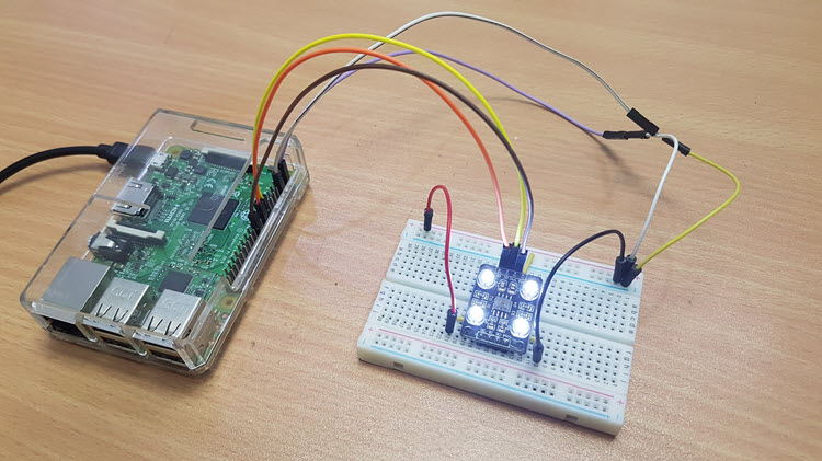
Continuing further in our Raspberry Pi exploration, we will do a project on Raspberry Pi based Color Detection. In this project, we will learn about TCS3200 Color Sensor and how the Raspberry Pi Color Sensor (TCS3200, to be specific) interface can be implemented for Color Detection.
Overview
Color Sensor detects or senses color. It is as simple as that. But how the Color Sensor actually detects the color is what makes things interesting.
There are many applications like object detection, product sorting, object tracking etc. All these and many other applications have Color Detection as a part of their system.
In color detection process, the Color Sensor is the main components or hardware. There are several types of Color Sensors that are used for different applications.
In the Raspberry Pi Color Sensor Interface Tutorial, I’ll be using the TCS3200 Color Sensor from TAOS (Texas Advanced Optoelectronic Solutions).
A Brief Note on TCS3200 Color Sensor
I have already made a project on TCS3200 Color Sensor. It is based on Arduino and the project is called ARDUINO BASED COLOR DETECTION.
In that project, I have spoken about basics of color sensors, how an LDR can be used as a Color Sensor and also a brief introduction to TCS3200 Color Sensor.
So, I strongly recommend you to go through that project (at least the Introduction to Color Sensor part) before continuing with Raspberry Pi Color Sensor Interface.
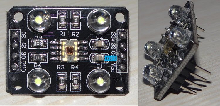
TCS3200 is one of the easily available color sensor that students and hobbyists can work on. It is basically a light to frequency converter i.e. based on color and intensity of the light falling on it, the frequency of its output signal varies.
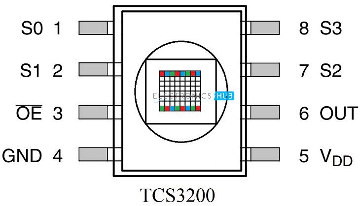
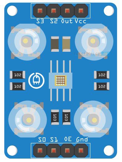
Pin Diagram of TCS3200
The following image shows the Pin Diagram of TCS3200. It is available in 8-pin SOIC Package.
Pin Description of TCS3200
- S0 and S1: S0 and S1 are Output Signal Frequency Scaling inputs. Using these pins, you can scale the output frequency to one of the three preset values. Table corresponding to S0 and S1 is given in the later sections.
- OE: It is the Output Enable Pins. It is an active LOW pin.
- GND: Power Supply Ground Pin.
- VDD: Power Supply Pin (usually, +5V).
- OUT: Output Pin, which produces a square ware of 50% Duty cycle and the frequency of the square wave is proportional to the intensity of the light.
- S2 and S3: S2 and S3 are the Photo Diode Selection Pins.
NOTE: The following table shows the different combinations of S0 and S1 inputs and corresponding output frequency scaling.
S0
S1
Output Frequency Scaling (f0)
Typical full-scale Frequency
L
L
Power Down
———-
L
H
2%
10 – 12 KHz
H
L
20%
100 – 120 KHz
H
H
100%
500 – 600 KHz
The table below shows the combination of inputs S2 and S3 and the corresponding Photo Diode selected.
S3
S4
Photodiode Type
L
L
Red
L
H
Blue
H
L
Clear (no filter)
H
H
Green
Circuit Diagram of Raspberry Pi Color Sensor Interface
The following Fritzing based image shows the connections diagram of the Raspberry Pi Color Sensor (TCS3200) interface.
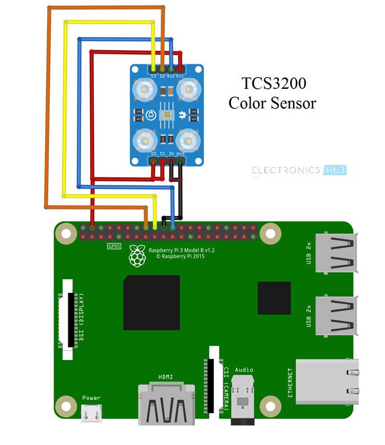
If the Pin Out of the TCS3200 Color Sensor in the above circuit diagram is not clear, you can use the following image as a reference.
Components Required
- Raspberry Pi
- TCS3200 Color Sensor
- Mini Breadboard
- Connecting Wires
- Power Supply
- Computer
Circuit Design
As mentioned earlier, TCS3200 Color Sensor has 8-pins. Connect Pins 1 and 2 i.e. S0 and S1 to +5V. Then connect theand GND to gnd of the Raspberry Pi.
Connect the VDD pin of the TCS3200 Color Sensor to +5V of Raspberry Pi. Pin 6 i.e. OUT pin of the Sensor is connected to Physical Pin 22 i.e. GPIO25 of Raspberry Pi.
Finally, connect the S2 and S3 of the color sensor to physical pins 16 and 18 i.e. GPIO23 and GPIO24 of the Raspberry Pi.
NOTE: Use a 5V Adapter to power the Raspberry Pi instead of connecting it to a computer.
Code
Code for RAW RGB Values
I’ll provide two codes for this project. Using the first code, you can display the RAW values of the RGB Gamut.
Code for Color Detection using Raspberry Pi and TCS3200 Color Sensor
Using the second code, you can implement a Color Detection Project. The code is calibrated to only three primary colors: Red, Green and Blue. But you can expand to a wide range of colors based on the results from the first code.
Working
The aim of this simple project is to understand the Raspberry Pi Color Sensor Interface and how can we make a Color Detection application using Raspberry Pi and TCS3200 Color Sensor.
Now, coming to the working, since both the S0 and S1 inputs of the TCS3200 Color Sensor are connected to +5V, the output frequency is scaled to 100% i.e. the output frequency will be in the range of 500 KHz to 600 KHz.
As S2 and S3 pins of the TCS3200 Color Sensor are used to select the Photo Diode, they are set in three different combination one after the other to get the RAW data of the Red, Blue and Green values.
Keeping these values as reference, the color detection program is written, where the Raspberry Pi correctly displays the name of the color placed in front of the sensor.
NOTE:
- The reference values in the second Python Script are dependent on the surrounding lighting. So, they may not work perfectly for you.
- In order to make a Color Detection Application, implement the first Python Script and note down values. Based on these values, you can develop your own Python Script for the Color Detector Application.
Applications
As already mentioned in the beginning, Color Sensors like TCS3200 can be implemented in a variety of projects and applications like:
- RGB LED Backlight Control
- Object Color Verification
- Product Sorting
- Industrial Automation
- Commercial Printing
- Health and Fitness

16 Responses
using this sensor to keep track of the ripening of my tomatoes
Cool. Nice thought and implementation.
can you teach me on detecting ripening?
Ravi, where can the board with the TCS3200 be obtained?
Hi,
Try Amazon for the Color Sensor. Search as “TCS3200” or “TCS230”.
Hi,
I made few changes to the code and it works better that way.
I changed the condition where you are qualifying the values
if green<red and blue<red:
print("red")
temp=1
elif red<green and blue<green:
print("green")
temp=1
elif green<blue and red<blue:
print("blue")
temp=1
Can i code to switch off my LED lights and detect colour
hello buddy use which software to detect the color?
Thanks for that! How would you modify the code to output the RGB values? We are trying to figure out how the read the color of a given liquid (non-transparent), and compare it to a given standard, so as to find out whether it is substantially different.
which software to be used to run the code
is there a way to get the value of color in range 0-255?
Hi Sir, how about the colour grading?
Hi! I’m just wondering what is the unit of the measurement of the raw RGB values?
how can i use 4 color sensor at a time in the above project how to implement that ??
Do you have a version of this code that works [the TCS3200] with a WiPy3? There aren’t any tutorials out there.
Sir can u please tell us the ‘name=main’ in the code
We are unable to get what it’s asking .