A Color Sensor, as the name suggests, is a device that senses or detects colors. A color sensor will use an external means of emitting light (like an array of white LEDs) and then analyse the reflected light from the object in order to determine its color.
Color sensors will give an accurate color of the object. There are a wide range of applications of color sensors like sorting objects by color, quality control systems, printer color enhancement etc.
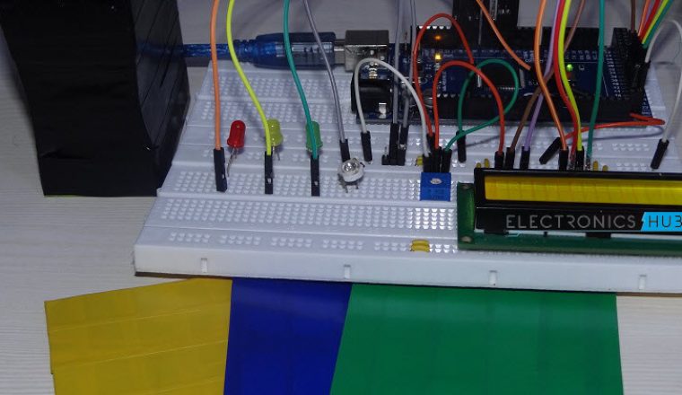
In this project, we have designed a simple Arduino Color Sensor application, which has an ability to detect different colors. We have used TCS3200 color sensors for this purpose. Introduction to color sensor, circuit diagram and working of the Arduino Color Sensor project are explained below.

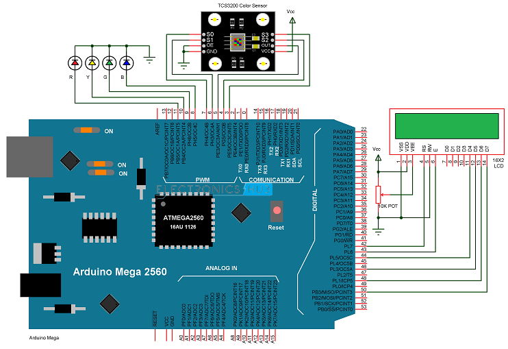
Arduino Based Color Detector Circuit Diagram
Components Required
- Arduino Mega [Buy Here]
- TCS3200 (RGB + Clear) Color Sensor Module
- Breadboard (Prototyping board)
- Power supply
- Connecting wires
NOTE: We have used Arduino Mega in this project as it has large number of I/O pins and we have connected many devices like TCS 3200 Color Sensor, 16X2 LCD Display and 4 LEDS. For simple Sensor Data using Serial Communication (Sensor information on the Serial Terminal), simple Arduino UNO can be used.
A Brief Introduction to Color Sensor
Technically speaking, colors are figments of our imagination. When we see a red apple, it means that it reflects that particular wavelength (~700 nm for Red) of the electromagnetic spectrum. This energy is absorbed by the eye and based on some chemical reaction, the brain says that particular wavelength is red color.
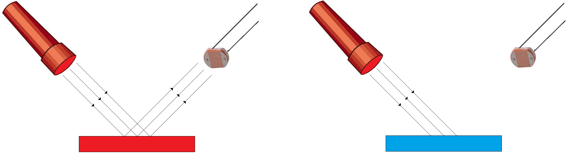
For computers, a sensors that differentiates between different colors will help in determining the color of the object. We will see a simple color sensor using a photo resistor (Light Dependent Resistor – LDR) and two different colored objects, say red and blue.
When we shine bright red light on both the objects, the red object will reflect the light whereas the blue object will absorb it. So, when red light is incident on both the red and blue objects, the red objects appears brightest to the LDR as it reflects most of the red light.

Similarly, when a bright blue light is incident on both the objects, the blue object will appear the brightest to the sensor. This method is just to understand the working of a color sensor and the actual results may not be accurate.
Practical Color Sensors like TCS3200 are a bit more complicated than this. The TCS3200 color sensor is a programmable color sensor which converts color light to frequency. The output frequency of the sensor is directly proportional to the intensity of the light reflected from the object.
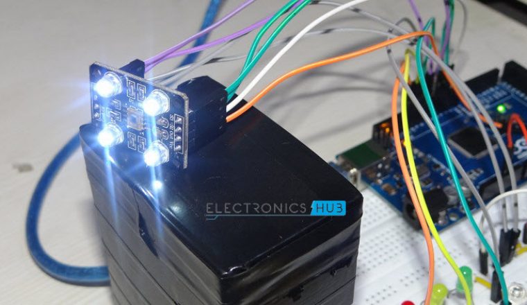
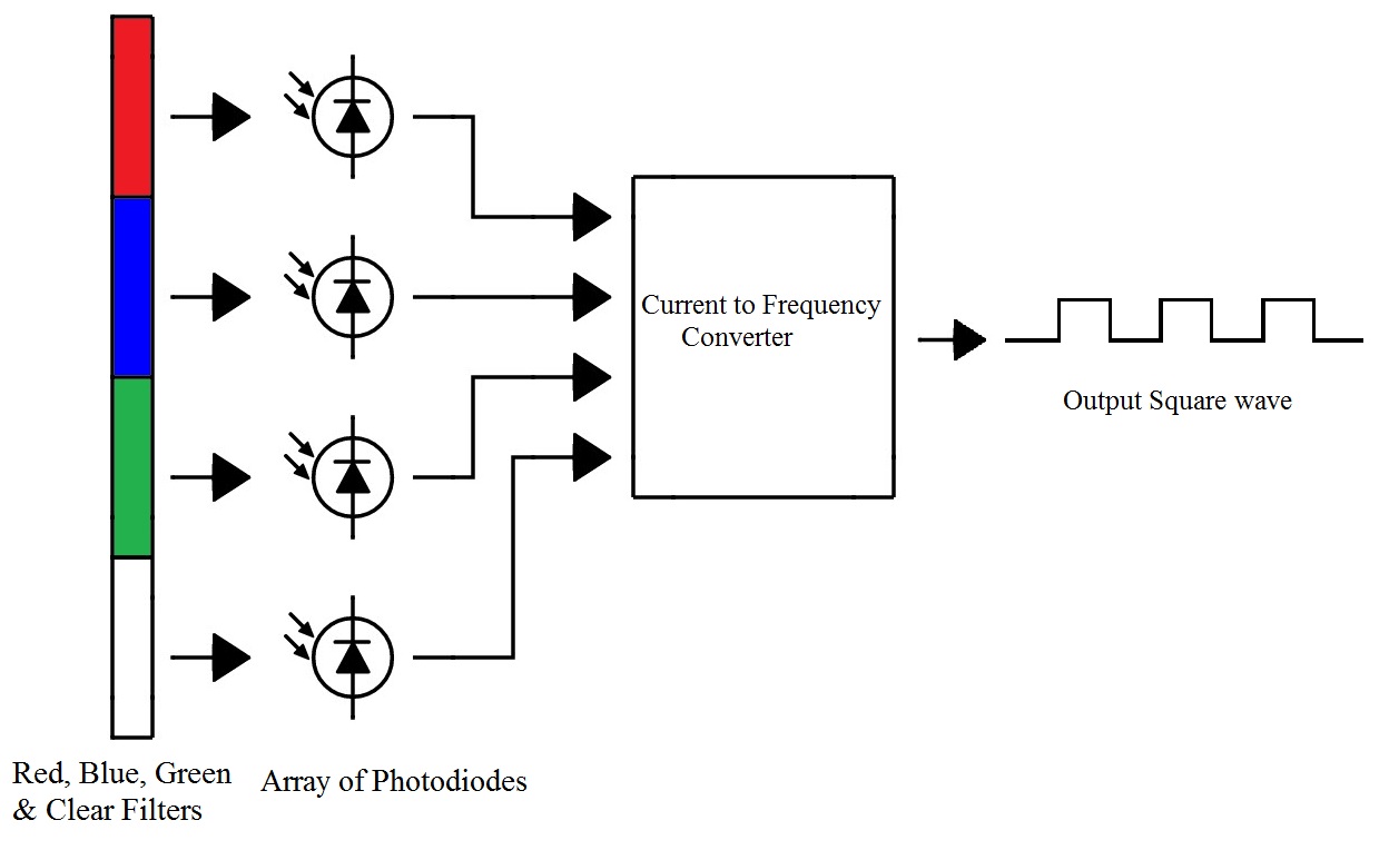
The TCS3200 Color Sensor Module has RGB + Clear Sensor along with 4 bright white LEDs embedded on the board. TCS3200 has an 8 x 8 array of photo diodes, 16 each for Red filters, Blue filters, Green filters and Clear (no filter).
The functional block diagram of TCS3200 Color Sensor is shown in the following image. It consists of color filters, photo diode array, current to frequency converter and final square wave output which can be given directly to a microcontroller.
 The TSC3200 Color Sensor IC is an 8 pin IC with SOC package. The following image shows the pin diagram of the Color Sensor IC. In that Pins 1 and 2 (S0 and S1) are output frequency scaling pins. Pin 3 is Output enable pin and is an active low pin. Pin 4 is GND.
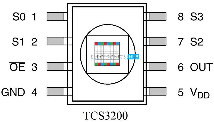
Pin 5 is the VDD pin and the maximum supply voltage is 5.5 V. Pin 6 is the output pin through which we can get the square wave output. Pins 7 and 8 (S2 and S3) are Photodiode selection pins.
Pins 1, 2 (S0, S1) and 7, 8 (S3, S4) are of special interest in TCS3200 Color Sensor. S0 and S1 are output frequency scaling pins. With these pins, the frequency of the output square wave can be scaled according to the application or microcontroller used.
The reason for scaling of output frequency is different microcontrollers have different timer configurations and there might be some limitations in the counter functionality of the microcontrollers. The following table shows the percentage of output scaling for different combinations of S0 and S1.
S0
S1
Output Frequency Scaling (f0)
Typical full-scale Frequency
L
L
Power Down
———-
L
H
2%
10 – 12 KHz
H
L
20%
100 – 120 KHz
H
H
100%
500 – 600 KHz
S3 and S4 are photo diode selection pins. They are used to select different photo diodes which are associated with different color filters (Red, Blue, Green and Clear). The following table shows different combinations of S3 and S4 for different types of photo diodes.
S3 and S4 are photo diode selection pins. They are used to select different photo diodes which are associated with different color filters (Red, Blue, Green and Clear). The following table shows different combinations of S3 and S4 for different types of photo diodes.
S3
S4
Photodiode Type
L
L
Red
L
H
Blue
H
L
Clear (no filter)
H
H
Green
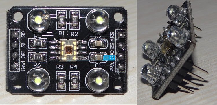
The TCS 3200 Color Sensor comes in the form of a Module with all the components like header pins, 4 White LEDs, Resistors and Capacitors in addition to the Actual TCS 3200 Color Sensor. The following image shows the real time Color Sensor Module.
Working of the Project
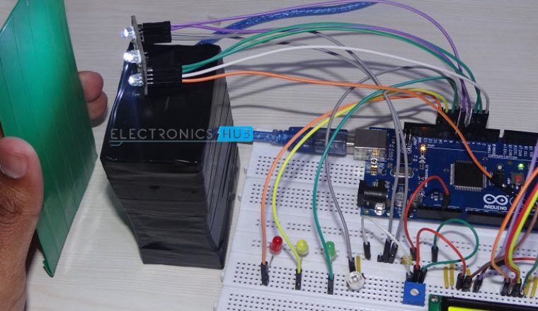
A simple Color Sensor using Arduino is developed in this project. The color sensor module senses the color in its surroundings. The working of the project is explained here.
As mentioned in the introduction to color sensor section, the TCS3200 Color Sensor has filters for Red, Blue, Green and Clear. The intensity of each color is represented as a frequency. In Arduino, we have fixed the output frequency scale to 100% by applying HIGH to S0 and S1 pins of the color sensor.
We have to use the S2 and S3 pin on the color sensor to select the type of photo diode i.e. red, green or blue. Whenever a particular Photo diode is selected, the PULSEIN feature of the Arduino is activated on the pin that is connected to the output of the Color Sensor.
This will help us to calculate the frequency of the output signal. The same process is repeated for all the three photo diodes: R, G and B. The frequency in all the cases is measured using the PULSEIN feature and is displayed on the Serial Terminal.
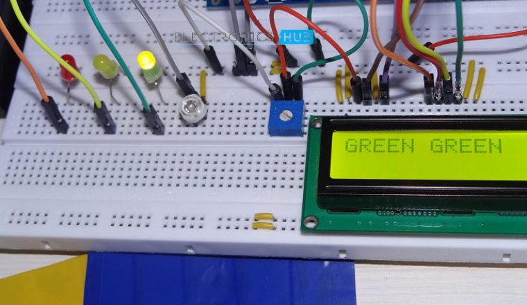
Additionally, this information can be used to identify the color placed in front of the sensor and display its color on the LCD and also light up the corresponding LED.
CODE
Applications
- Color Sensors have a wide range of applications in the fields of image processing, digital signal processing, object detection, color identification, etc.
- In industries, Color sensors are often used in sorting objects based on color.
Recommended read:

12 Responses
Sir, can i replace arduino mega with arduino uno? And can you pleaae show me the code? Ill be needing your answer for i will be implementing this project.
Hi,
Yes. You can replace Mega with UNO. But you will be limited to either LCD Display (for showing the color) or the individual LEDs.
In the code, modify the I/O Pins as per UNOs connections.
hello sir,
can you please send me the arduino code of this project ?
Code is uploaded.
Where is coding?
Code is uploaded.
Can you please send me the code
Code is uploaded.
Sir,this is a very good project!
but i wanted to replace arduino mega with arduino uno as the cost of arduino mega is pretty high….
So what are the changes that we make in circuit diagram and the code??
Can you please send me the code asap as ill be implementing this project
Thank you.
Could I replace arduino mega with arduino nano? I assume I would be limited to just LED lights as indicators which is fine, I am new to this and a Nano is what I have access to right now
Hi sir..do you have a coding on what if the sensor detect red, the motor dc will stop..if detect green it will stop
Please provide the code for this .This is a very good project .want to implement