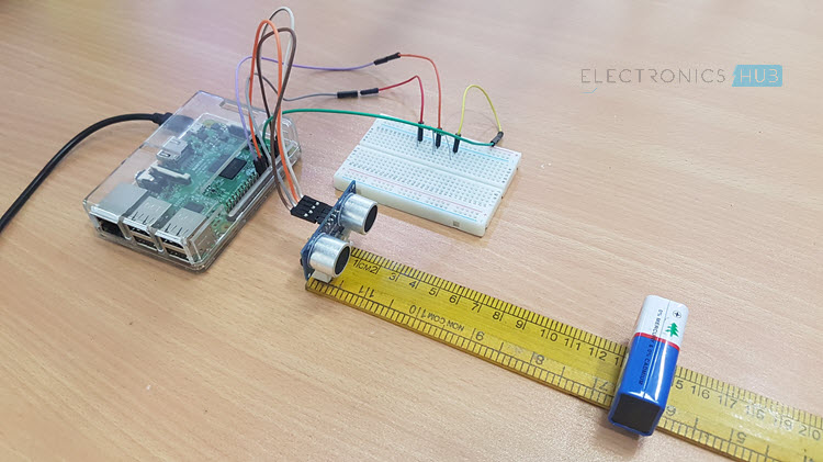
Ultrasonic Sensors, particularly HC-SR04 Ultrasonic Sensor, are very popular among electronic hobbyists and are frequently used in a variety of projects like Obstacle Avoiding Robot, Distance Measurement, Proximity Detection and so forth. In this project, we will learn about HC-SR04 Ultrasonic and see how to interface one with Raspberry Pi.
Overview
The HC-SR04 Ultrasonic Sensor is marketed as a Ranging Module as it can be accurately used for measuring distances in the range of 2cm to 400cm with an accuracy of 3mm.
The range of this Ultrasonic Sensor seems very less but it is sufficient for the applications it is implemented in i.e. Proximity Detection and Obstacle Avoiding, for example.
I have already used this Ultrasonic Sensor several of my previous projects like: PORTABLE ULTRASONIC RANGE METER and OBSTACLE AVOIDING ROBOT.
The Raspberry Pi Ultrasonic Sensor Interface is different from interfacing LED, Button, LCD, Motors, etc. with Raspberry Pi. This is because the output of the HC-SR04 Ultrasonic Sensor is at a 5V logic level whereas the Raspberry Pi works on a 3.3V logic level.
A Brief Note on Ultrasonic Sensors
If you refer to the previous projects based on the Ultrasonic Sensor Module, I have briefly discussed about the working of the module. We will take a brief note once again before continuing with Raspberry Pi Ultrasonic Sensor Interface.
The HC-SR04 Ultrasonic Sensor (or any Ultrasonic Sensor for that matter), works on the principle that is similar to RADAR and SONOR i.e. transmits a signal and analyzes the target by capturing the reflected signals.
How HC-SR04 Ultrasonic Sensor Works?
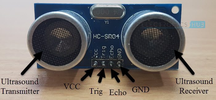
Before getting into the working of an Ultrasonic Sensor, lets us see the parts and pins of the HC-SR04 Ultrasonic Sensor.
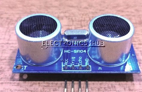
It basically consists of three parts: an ultrasonic transmitter, a control circuit and an ultrasonic receiver. Coming to the pins of the HC-SR04 Sensor, it has only four pins namely VCC, TRIG (Trigger), ECHO (Echo) and GND.
The basic principle behind the Ultrasonic Sensor is described here. The Ultrasonic Transmitter in the Sensor generates a 40 KHz Ultrasound. This signal then propagates through air and if there is any obstacle in its path, the signal hits the object and bounces back.
This bounced signal is then collected by the Ultrasonic Receiver. Based on the signal’s time of travel, you can calculate the distance of the object as you already know the speed of sound.
How to Calculate Distance?
We will now see how to measure the distance of an object using HC-SR04 Ultrasonic Sensor. In order to send the 40 KHz Ultrasound, the TRIG Pin of the Ultrasonic Sensor must be held HIGH for a minimum duration of 10µS.
After this, the Ultrasonic Transmitter, will transmits a burst of 8-pulses of ultrasound at 40 KHz. Immediately, the control circuit in the sensor will change the state of the ECHO pin to HIGH. This pins stays HIGH until the ultrasound hits an object and returns to the Ultrasonic Receiver.
Based on the Time for which the Echo Pin stays HIGH, you can calculate the distance between the sensor and the object.
For example, if we calculated the time for which ECHO is HIGH as 588µS, then you can calculate the distance with the help of the speed of sound, which is equal to 340m/s.
Distance = Velocity of Sound / (Time/2) = 340m/s / (588µS /2) = 10cm.
Raspberry Pi Ultrasonic Sensor Interface
Now that we have seen how the HC-SR04 Ultrasonic Sensor works, we will proceed with interfacing it with Raspberry Pi. Before making the connections, you have to note a point that Raspberry Pi works at 3.3V Logic while the HC-SR04 Ultrasonic Sensor works at 5V.
The Raspberry Pi needs to read the Echo pin to calculate the time and hence the corresponding GPIO pin on the Raspberry Pi must be configured as Input So, before connecting the Echo Pin to the Raspberry Pi, it must be given to a level converter.
More information about this is provided in the circuit design part.
Circuit Diagram
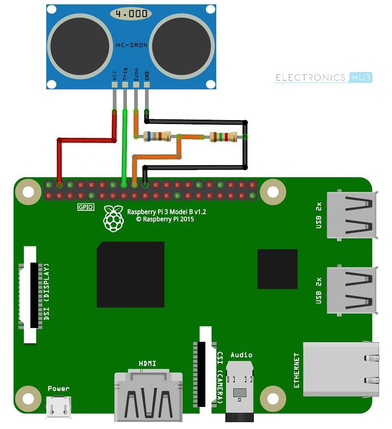
The following image shows the connections between the Raspberry Pi and the HC-SR04 Ultrasonic Sensor. This circuit diagram is made with Fritzing Software.
Components Required
- Raspberry Pi 3 Model B
- HC-SR04 Ultrasonic Sensor
- 680 Ω Resistor (1/4 Watt)
- 1.5 KΩ Resistor (1/4 Watt)
- Connecting Wires
- Mini Breadboard
- Power Supply
- Computer
Circuit Design
Connect the Trig Pin of the HC-SR04 Ultrasonic Sensor to the Physical Pin 16 i.e. GPIO23 of the Raspberry Pi. Use a combination of 680Ω and 1.5 KΩ Resistor to convert the Echo pin to 3.3V Logic (approximately) and connect it to Physical Pin 18 i.e. GPIO24 of the Raspberry Pi.
Finally, provide the +5V and GND connections to the Ultrasonic Sensor from the Raspberry Pi Pins.
Code
The following Python Script is used in the HC-SR04 Ultrasonic Sensor and Raspberry Pi Interface.
Working
A simple project is implemented here, where we have seen how to interface an HC-SR04 Ultrasonic Sensor with Raspberry Pi. The working of the project is already explained in the How HC-SR04 Ultrasonic Sensor Works section.
A simple calculation program is written in Python to detect the HIGH on Echo Pin and produce an equivalent distance.
Applications
In this project, we have seen how to interface HC-SR04 Ultrasonic Sensor with Raspberry Pi. This setup can be used in a lot applications like:
- Obstacle Avoiding
- Proximity Detection
- Distance Measurement
- Range Meter
