In this tutorial, we will see the Pinouts of both NodeMCU board as well as the ESP-12E Module, which is the base board for NodeMCU. The ESP12-E Pinout will be helpful if you are developing your own hardware and understanding the NodeMCU Pinout is very useful if you are working with ESP8266 NodeMCU board.
NodeMCU Pinout and ESP-12E Pinout
Even though the concept of Internet of Things (IoT) has been there for several years, it really took off once the DIY community started investing in it. To aid low-cost and easy to implement IoT systems, you need both the supporting hardware as well as good software.
This is where Espressif Systems came into picture with a bang. The ESP8266 SoC, released back in 2014, has been the go-to chip for IoT related projects in the DIY community.
Several third-party manufacturers took the ESP8266 SoC and started developing small modules and boards, that can be easily integrated into our existing hobbyist setup consisting mainly of Arduino.
One of the popular ESP8266 based module is the ESP-01, developed by Ai-Thinker. This is a simple board with the ESP8266 SoC, a flash memory and few pins to connect to other devices like Arduino.
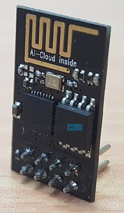
This is a great board to start with ESP8266 but there are a few limitations like the pins are not breadboard friendly, only two GPIO pins, need for an USB to UART converter module to program etc.
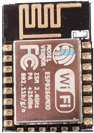
So, what manufacturers started doing is instead of using the vanilla version of the ESP8266 Module, which is the ESP-01, they started using a slightly advanced version called the ESP-12E, which is also from Ai-Thinker.
The good thing about ESP-12E is it has more GPIO Pins and the PCB comes with castellated edges so that you can easily solder this board on to your own design.
ESP-12E Module
Ai-Thinker’s ESP-12E is a Wi-Fi Module based on ESP8266EX SoC. The ESP8266EX SoC is a Wi-Fi chip based on Tensilica’s L106 Diamond 32-bit Processor and an integrated Wi-Fi MAC, with support for full TCP/IP Stack.
Since it has a Microcontroller (in the form of Tensilica’s L106 Diamond), the ESP-12E can be used as either a stand-alone device with its Wi-Fi connectivity and GPIO Pins or it can be used as a Wi-Fi adapter for other microcontrollers like Arduino, for example, through UART interface.
The ESP-12E Module consists of ESP8266 SoC, 4MB of SPI Flash, 26 MHz Crystal, PCB antenna and some RF related components. As you can see from the image, the ESP-12E has a lot more pins than ESP-01 Module and all the pins on the PCB are edge castellated.
ESP-12E Pinout
If you are interested in designing your own breakout board for ESP-12E Module, then the following ESP-12E Pinout image will be very useful for you. As you can see, there are 22 pins on the ESP-12E Module.
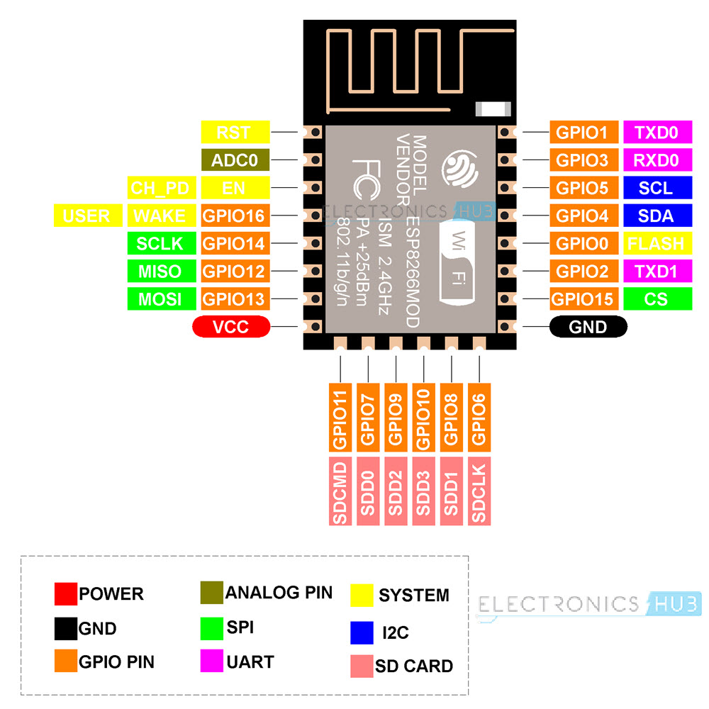
The above pinout diagram of ESP-12E Module describes all the pins and their alternative functions as well. The following table describes the pins of ESP-12E Module.
| Pin | Function |
| RST | Reset the Module |
| ADC0 | ADC Pin with 10-bit resolution |
| EN | Chip Enable Pin (active HIGH) |
| GPIO16 | GPIO16 pin (wake pin from deep sleep mode) |
| GPIO14 | GPIO14 pin (HSPI_CLK) |
| GPIO12 | GPIO12 pin (HSPI_MISO) |
| GPIO13 | GPIO13 pin (HSPI_MOSI) |
| VCC | 3.3V Power Supply (max 3.6V) |
| SDCMD | SDIO CMD (GPIO11) |
| SDD0 | SDIO Data 0 (GPIO7) |
| SDD2 | SDIO Data 2 (GPIO9) |
| SDD3 | SDIO Data 3 (GPIO10) |
| SDD1 | SDIO Data 1 (GPIO8) |
| SCCLK | SDIO CLK (GPIO6) |
| GND | Ground Pin |
| GPIO15 | GPIO15 pin (HSPI_CS) |
| GPIO2 | GPIO2 pin (TXD1) |
| Flash | Flash Pin (GPIO0) |
| GPIO4 | GPIO4 pin (SDA – software I2C) |
| GPIO5 | GPIO5 pin (SCL – software I2C) |
| RXD0 | UART0 RXD pin (GPIO3) |
| TXD0 | UART0 TXD (GPIO1) |
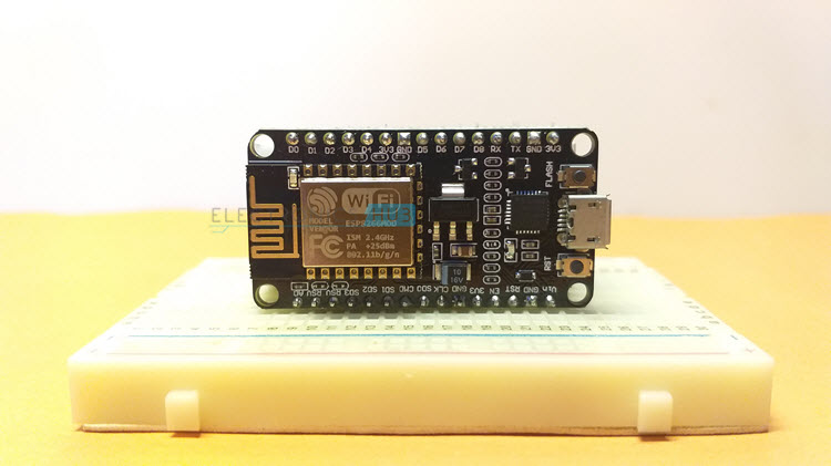
ESP8266 NodeMCU Breakout Board
Using the ESP-12E Module as the base board, the NodeMCU team developed a breakout board for their NodeMCU Firmware project and made the design open source. I already discussed about the on-board peripherals of the ESP-12E NodeMCU board in the “Getting Started with NodeMCU” tutorial.
In that tutorial, I just gave a simple pinout image of NodeMCU without any in depth explanation. That is what this tutorial is for. First, we will see the pinout diagram and then understand the functions of each pin.
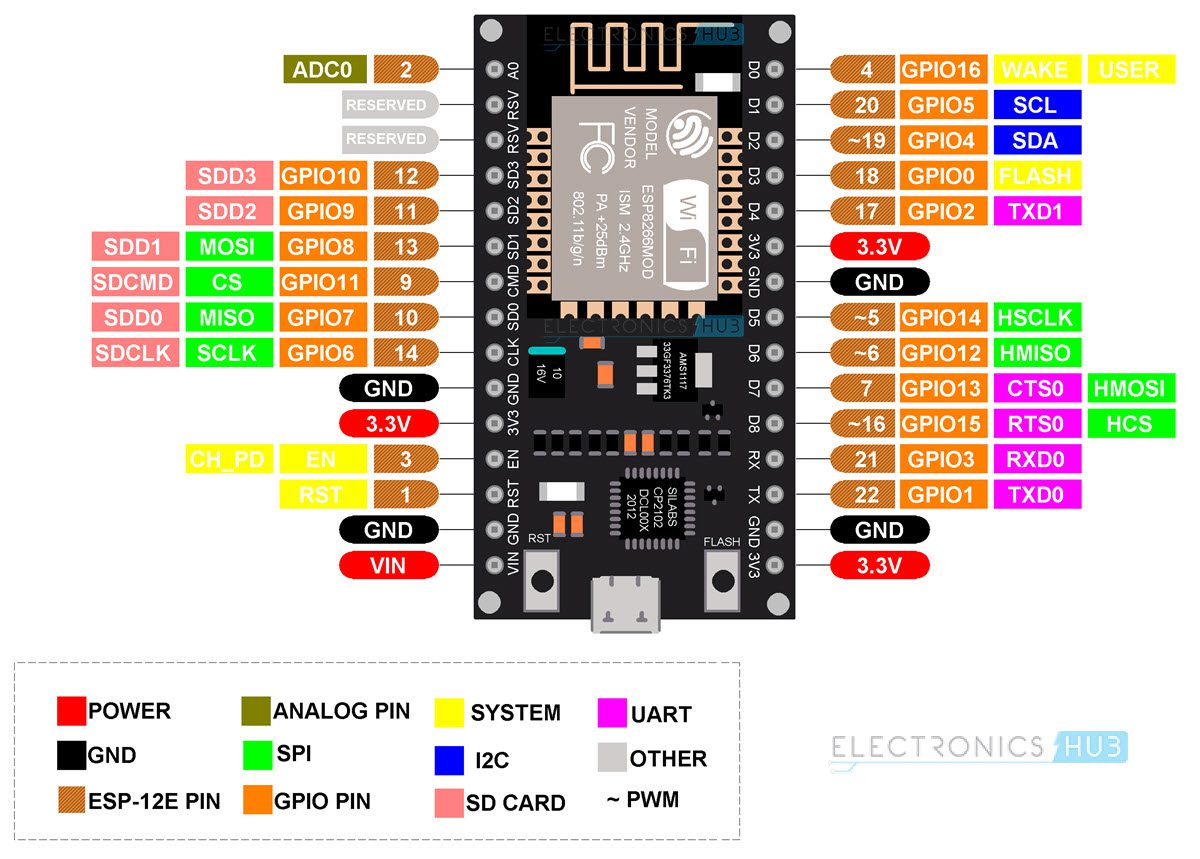
NodeMCU Pinout
The following image shows the pinout for NodeMCU board. A typical NodeMCU board (if it is based on the original NodeMCU Devkit design) has 30 pins. In this, 8 pins are related to power and 2 are reserved. The remaining 20 pins are associated with pins of ESP-12E Module.
A brief description of the pins is given in the following table.
|
Pin |
Description | Alternate Functions |
Default |
|
ADC0 |
Analog Input | ADC0 | |
|
Reserved |
|||
|
Reserved |
|||
| SDD3 | SDIO Data 3 | GPIO10 |
SDD3 |
|
SDD2 |
SDIO Data 2 | GPIO9 | SDD2 |
| SDD1 | SDIO Data 1 | GPIO8 |
SDD1 |
|
SDDCMD |
SDIO CMD | GPIO11 | SDDCMD |
| SDD0 | SDIO Data 0 | GPIO7 |
SDD0 |
|
SDCLK |
SDIO CLK | GPIO6 | SDCLK |
| GND |
Ground |
||
|
3.3V |
3.3V Output | ||
| EN | Chip Enable (Active HIGH) |
|
|
|
RST |
Reset (Active LOW) | ||
| GND |
Ground |
||
|
VIN |
5V Input to 3.3V Regulator | ||
| 3.3V | 3.3V Output |
|
|
|
GND |
Ground | ||
| TXD0 | UART0 TXD | GPIO1 |
TXD0 |
|
RXD0 |
USRT0 RXD | GPIO3 | RXD0 |
| GPIO15 | GPIO15 | HSPI_CS / RTS0 |
GPIO15 |
|
GPIO13 |
GPIO13 | HSPI_MOSI / CTS0 | GPIO13 |
| GPIO12 | GPIO12 | HSPI_MISO |
GPIO12 |
|
GPIO14 |
GPIO14 | HSPI_SCK | GPIO14 |
| GND | Ground |
|
|
|
3.3V |
3.3V Output | ||
| GPIO2 | GPIO2 | UART1 TXD |
GPIO2 |
|
Flash |
Flash | GPIO0 | Flash |
| GPIO4 | GPIO4 | Software SDA (I2C) |
GPIO4 |
|
GPIO5 |
GPIO5 | Software SCL (I2C) | GPIO5 |
| GPIO16 | GPIO16 | Wake (deep sleep) |
GPIO16 |
I will discuss about all the available peripherals, what pins to use, how to power the board etc. in the next section.
Power, Peripherals and Pins
How to Power NodeMCU?
There are two ways to power the NodeMCU board. One is through the micro-USB port and the other is through VIN pin. Note that ESP8266EX SoC is compatible with only 3.3V. So, the NodeMCU board has 3.3V Regulator IC (AMS1117 – 3.3).
If you have regulated 5V power, then you can apply this to the VIN pin. There are three 3.3V pins, which are connected to the 3.3V output of the regulator.
What Peripherals are available on NodeMCU?
Strictly speaking, this is related to the ESP8266EX SoC. Keeping that in mind, let us see all the peripherals that are available on the NodeMCU.
GPIO
The ESP8266EX has 17 GPIO pins. But not all them available for the user as some of these are used for their alternative functions (like UART, SDIO, SPI etc.) in NodeMCU (ESP-12E Module).
We will see the available GPIO Pins on NodeMCU after looking at all the other peripherals.
SPI
There are two SPI Interfaces on ESP8266EX SoC (SPI and HSPI). Both support Master and Slave Operations. Master mode clock can be configured to 80 MHz while slave mode clock is up to 20 MHz.
- SCLK – GPIO6 (Not Available)
- MISO – GPIO7 (Not Available)
- MOSI – GPIO8 (Not Available)
- CS – GPIO11 (Not Available)
- HSPI_CLK – GPIO14
- HSPI_MISO – GPIO12
- HSPI_MOSI – GPIO13
- HSPI_CS – GPIO15
GPIO pins for SPI are multiplexed with some SDIO pins. Also, there is a 4MB SPI Flash on the ESP-12E Module connected through SPI Pins. So, you do not have access to SPI pins. You can only used HSPI pins for SPI communication.
I2C
Hardware I2C is not available in ESP8266 but is can implemented through software. GPIO4 and GPIO5 can be used as SDA and SCL as they do not have any other alternative functions.
UART
ESP8266EX has two hardware UARTs (UART0 and UART1) with baud rates up to 115200. In this, UART0 can be used for communication and it has data flow control as well. UART1 has only TX pin (its RX pin is used by SDD1) so, it can used for data logging.
- UART0 TX – GPIO3
- UART0 RX – GPIO1
- UART0 RTS – GPIO15
- UART0 CTS – GPIO13
- UART1 TX – GPIO2
- UART1 RX – GPIO8 (Not Available)
Additional Features
All the GPIO pins except GPIO16 support Interrupts.
There are two on-board LEDs on the NodeMCU Board. One LED is on the ESP-12E Module and is connected to GPIO2 and the other LED is on the NodeMCU Board and this is connected to GPIO16.
So, What GPIO Pins on NodeMCU are available?
If you consider all the information presented until now, you can deduce the number of GPIO pins available for user. First of all, GPIO6 – GPIO11 are used for SPI Flash. So, these are not available for user.
Also, GPIO1 and GPIO3 are used as UART TX and RX Pins, which also rules them out. So, out of 17 GPIO pins, 8 are already used for other purposes. This leaves us with 9 pins. These pins are marked as D0 to D8 on NodeMCU Board.
The following table shows the available GPIO Pins on NodeMCU.
|
GPIO Pin |
NodeMCU Pin |
Information |
|
0 |
D3 | Pulled HIGH and connected to Flash Button |
| 1 | TX |
Do not use while TXing |
|
2 |
D4 | |
| 3 | RX |
Do not use while RXing |
|
4 |
D2 | I2C SDA |
| 5 | D1 |
I2C SCL |
|
6 – 11 |
– | Connected to SPI Flash |
| 12 | D6 |
|
|
13 |
D7 | |
| 14 | D5 |
|
|
15 |
D8 | Pulled LOW |
| 16 | D0 |
Used to wake from deep sleep. No interrupt, I2C, PWM |
Boot Mode Selection Pins
The following Pins for selecting the boot mode.
|
GPIO 0 |
GPIO 2 | GPIO 15 | Boot Mode |
| LOW | HIGH | LOW |
UART Bootloader |
|
HIGH |
HIGH | LOW | Boot from SPI Flash |
| x | x | HIGH |
Boot from SDIO |
Conclusion
You learned about ESP-12E Module, ESP-12E Pinout, NodeMCU Board, NodeMCU Pinout, important pin related information of NodeMCU.

2 Responses
Can I supply 5v 5amp power to nodemcu?
yes you can, but 5v1a supply would be way smoother