A control system is defined as the collection of devices which are used to control or regulate the output of other system. To attain the stability and to auto correct the errors occurred in the output of the system, we depend on feedback technique.
The feedback may be of negative magnitude and positive magnitude. Open loop control systems have no feedback signal, so they are also called “Non feedback control systems”. Closed loop control systems are connected with a feedback signal to attain stability, so they are also called “Feedback systems”.
Based on nature of feedback loop, the closed loop control systems are classified into two types 1) positive feedback control system and 2) Negative feedback control systems.
In this tutorial, we clearly discuss about the negative feedback systems and their types, features etc.
Outline
ToggleNegative Feedback System
A negative feedback system is defined as the negative feedback connected closed loop system. When the output of the system is increased more than the desired output, instead of increasing, we should control the output by decreasing the input. This can be achieved by using a negative feedback control.
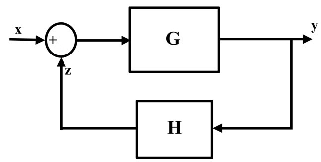
The block diagram of negative feedback system is shown below. As the negative feedback loop decreases the input signal level, it is also called as “Degenerative feedback”.
Negative feedback block diagram
A simple block diagram of negative feedback loop is shown below. In this, X is the input signal and Y is the output signal for the system G, and H is the negative feedback loop for controlling the input signal which is summed at the input signal.
Example for negative feedback control system
The negative feedback loop is used to control or decrease the excess output of the system, by subtracting some amount of signal from input. An electronic amplifier is the example of negative feedback system.
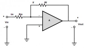
A negative feedback amplifier is designed by connecting the input signal to the inverting pin of the op-amp and connecting some amount of output signal to the input, as feedback loop through a resistive path.
If Vin is the input signal of the op-amp through resistor Rin and Rf is the feedback resistor, then the output of the system is controlled by feeding back the signal of a gain ratio of Rf ÷ Rin.
When the input signal is positive, the output of the op-amp becomes negative and the negative feedback will regularize the op-amp to be in a state of desired output condition.
Similarly, if we connect negative input to the op-amp, then it’s output becomes positive (inverted output). When the negative feedback is provided to the input, it adds up the input signal and maintains the desired output.
The negative feed backed control systems doesn’t oscillate by themselves, because they are controlled by inverting operation of input and feedback loop.
So these systems are considered to be more stable than positive control systems. Negative feedback systems are more immune to the fluctuations and variations of the different system components.
Transfer Function
The working and efficiency of a negative feedback control system can be explained by using its transfer function. A ‘Transfer function’ is defined as the relative function between input and outputs.
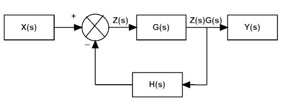
In a negative feedback system, an intermediate signal is defined as Z, as shown below.
The output of the system is equal to Y(s)
Y (s) = Z (s) . G (s)
Z (s) = X (s) – Y (s) . H (s)
X (s) = Z (s) + Y (s) . H (s)
X (s) = Z (s) + Z (s) . G (s) . H (s)
So (Y (s))/(X (s)) = (Z (s).G (s))/(Z (s)+ Z(s)G(s)H(s))
(Y (s))/(X (s)) = (G (s))/(1+ G(s).H(s))
So the transfer function of the negative feedback loop is equal to (G (s))/(1+ G(s).H(s)).
Example problem
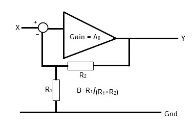
Find the closed loop gain and circuit behavior of a negative feedback loop amplifier, when the feedback resistors are 1K and 10K.
In the given example the feedback loop has resistors 1K and 10K connected in parallel. i.e.
R1 = 1kΩ
R2 = 10kΩ
Now the feedback loop gain can be calculated as
β = R1 / (R1+R2)
= 0.0909 = 1 / 11
The closed loop gain of the system can be calculated as
Ac = 1/β
= 1 / 0.0909
= 11
Analyzing the closed loop behavior
We already know that the closed loop gain is 11 and assuming the open loop gain as 1000, by comparing the closed loop gain with the transfer function formula , we get
= (G (s))/(1+ G(s).H(s) )
= A_o/(1+ A_c.β)
= 1000/ (1 + 1000 * 11-1)
= 10.88.
So the actual gain of the closed loop amplifier is 10.88, but the gain is 11, in practical.
When negative feedback is applied to the signal, how would an open loop gain will affect the closed loop gain of a system?
Let’s say the open loop gain of the system as 2000, then finding the closed loop gain we get
= Ao/(1+ Ac.β)
= 5000 / (1 + 5000 * 11-1)
= 10.97.
This means, if we increase in the open loop gain 400%, the closed loop gain will change 0.8%.
This means the gain of a system doesn’t depends upon the temperature and other variables. It only depends on the feedback loop gain only.
Classification of negative feedback
Based on the amplification process of input signal and on desired output condition, the feedback loops are classified into 4 different types. They are
- Series – shunt configuration
- Shunt – shunt configuration
- Series – series configuration
- Shunt – series configuration
Series – shunt configuration
This is also called as “Voltage controlled voltage source” or “Voltage in and voltage out configuration”. In this series voltage feedback system, the error voltage signal is fed back to the input voltage signal as shunt or in series connection. The block diagram for series – shunt connection is shown below.
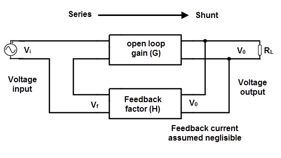
Av = Vout / Vin.
Shunt – series configuration
This is also called as “Current controlled current source” or “Current in and current out configuration”. In this shunt current feedback system, the error current signal is fed back to the input current signal as shunt or parallel connection. The block diagram for shunt – shunt connection is shown below.
In this shunt series configuration system, both input and outputs are current signals. So it acts as a true current amplifier with transfer gain of
Ai = Iout / Iin.
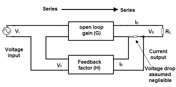
Series – Series Configuration
This is also called as “voltage controlled current source” or “voltage in and current out configuration”. In this series current feedback system, the error current signal is fed back to the input current signal as series connection.
The block diagram for series – series configuration is shown below.
In this series – series configuration system, input signal is voltage and output is current signal. So it functions as trans-conductor with transfer gain of Av = Vout / Iin.
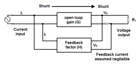
Shunt – Shunt configuration
This is also called as “current controlled voltage source” or “current in and voltage out configuration”. In this series current feedback system, the error current signal is fed back to the input current signal as shunt connection. The block diagram for shunt – shunt configuration is shown below.
In this shunt – shunt configuration system, input signal is current and output is voltage signal. So it functions as trans-resistor with transfer gain of
Av = Iout / Vin.
Effects of negative feed back
The negative feedback causes some change in system behavior and system properties. They are
- Reduces gain
- Reduces gain sensitivity
- Reduces non linear distortion
- Extends bandwidth
- Reduces noise effect
- Enhances the input and output impedances
- Increases input resistance
Gain reduction
We know that the closed loop gain is equal to
Closed loop gain = (open loop gain)/((1+open loop gain*B))
Ac = Ao / (1 + Ao * B) where B is the feedback factor.
If B > 0, then the denominator obviously becomes greater than 1, so the loop gain will be reduced by negative feedback.
Reduction in linear distortion
Consider the voltage characteristics of a system with feedback (closed loop system) and without feedback (open loop feedback) and assume that the voltage transfer characteristics of open loop system is linear.
When the gain of open loop system changes from 1000 to 100 and then 100 to 0 then plot the voltage characteristics Vo/Vi and apply negative feedback, B = 0.01.
For the change of 1000 to 100, the closed loop gain is 1000 / (1000 + 1000*0.01) = 90.9
For the change of 100 to 0, the closed loop gain is 100 / (100 + 100*0.01) = 50
This means, the closed loop gain of the system changes from 90.7 to 50 and then from 50 to 0. Now if we plot the closed loop gain , we can observe that the change in gain is more for closed loop, compared to that of open loop.
This means that the negative feedback will reduce the linear distortion.
Increases bandwidth
If we consider a hi-frequency amplifier with dominant pole ‘wh’ then by calculating the gain of the system, we get
A = A0 / (1 + (s / Wh)).
Calculating the gain after applying the negative feedback, Af = A / (1 + AB) where B is feedback factor.
Af = A / (1 + AB)
= (Ao / (1 + (s / (wh * (1 +Ao B)))))
From the above equation, we can observe that
Aof = (Ao / (1 + Ao B))
Whigh f = Wh * (1 + Ao B) – – – – -> (1)
From equation 1, we see the high frequency 3-db point is increased by a factor of (1 + Ao B) when we apply the negative feedback.
Using the same transfer function, analysis , if we find the transfer function for low frequency point, then
Wlow f = Wlow / (1 + Ao B)
So, the bandwidth which is the difference between high and low frequency points, is increased by using negative feedback.

