In this project, I’ll show you how the MPU6050 Sensor works and also how to interface Arduino with MPU6050. We will be interfacing an MPU-6050 breakout board with Arduino UNO and read the values from the Accelerometer and Gyroscope.
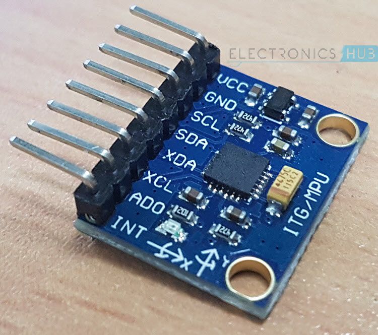
Before going in to the project, you need to understand a few basics of the MPU6050 Sensor. MPU-6050 is an IMU Sensor that contains a MEMS (Microelectromechanical System) Accelerometer and MEMS Gyroscope on a single chip.
Here, IMU Sensor, where IMU stands for Inertial Measurement Unit, is a device that measures the specific force using Accelerometer, angular rate using Gyroscope and magnetic field using Magnetometers.
IMU Sensors are used in self-balancing robots, aircrafts, mobile phones, tablets, spacecraft, satellites, drones, UAVs (unmanned aerial vehicles) etc. for guidance, position detection, orientation detection, motion tracking and flight control.
Arduino and MPU6050
The two common IMUs are ADXL 335 Accelerometer and MPU-6050. The ADXL 335 contains a 3-axis Accelerometer.
In case of MPU-6050, it is a six-axis motion tracking device that combines a 3-axis Accelerometer and a 3-axis Gyroscope on a single chip. We will see more details about MPU6050 in the next section.
Introduction to the MPU6050 Sensor
The MPU-6050 is a six-axis motion tracking device developed by InvenSense. The main features of the MPU6050 device are mentioned below.
- Three – axis Accelerometer
- Three – axis Gyroscope
- Digital Output Temperature Sensor
- Six 16-bit ADC (three for Accelerometer and three for Gyro)
- Integrated Digital Motion Processor (DMP)
- 1024B FIFO Buffer
The six-axis MPU-6050 is some time called as a 6 DoF (six Degrees of Freedom) device, as it provides six output values (three from Accelerometer and three from Gyro). The MPU-6050 can communicate using I2C Protocol.
Digital Motion Processor or the DMP is an embedded processor that can reduce the computational load from the host processor, like an Arduino, by acquiring and processing data from Accelerometer, Gyroscope and an external Magnetometer.
Interfacing MPU6050 with Arduino
As mentioned earlier, the MPU6050 supports only I2C Communication and hence, it must be connected only to the I2C Pins of the Arduino. The I2C pins of Arduino are multiplexed with the analog input pins A4 and A5 i.e. A4 is SDA and A5 is SCL.
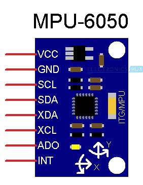
Coming to the MPU6050, we have used a normal breakout board that provided eight pins. The above image shows the schematic representation of the MPU6050 Breakout board.
In this, we will be using the SCL, SDA and the INT pins to connect with Arduino.
Components Required
Hardware
- Arduino UNO [Buy Here]
- MPU6050 Breakout Board
- Connecting Wires
Software
- Arduino IDE
- Processing (for 3D Visualization)
Circuit Diagram
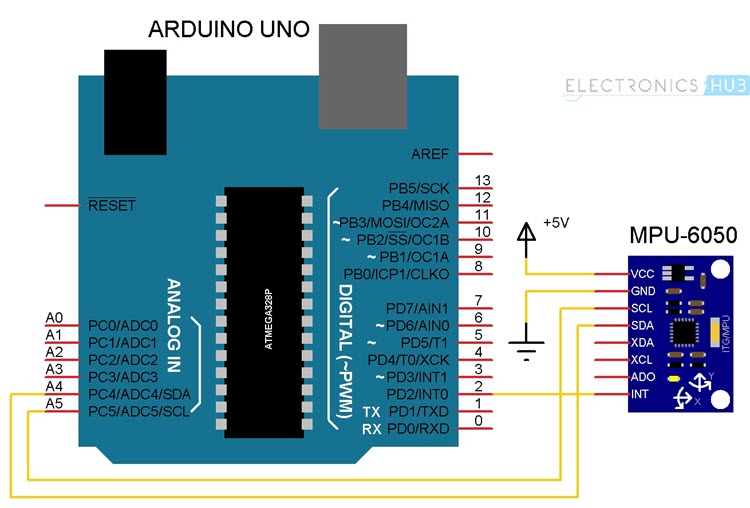
The following image shows the circuit diagram for interfacing MPU6050 with Arduino UNO. As mentioned earlier, the interface between MPU6050 and Arduino must be implemented using I2C Protocol.
Hence, the SCL Pin of the Arduino (A5) is connected to the SCL Pin of the MPU6050. Similarly, the SDA Pin of the Arduino (A4) is connected to the SDA Pin of the MPU6050 board.
Additionally, we will be using the Interrupt feature of the MPU6050 to indicate (or interrupt) Arduino when the 1024 Byte FIFO buffer is full. So, connect the INT pin of the MPU6050 to the external interrupt 0 (INT0) pin of Arduino UNO i.e. Pin 2.
NOTE: In I2C Communication, the MPU-6050 always acts as a slave.
Reading RAW Values from MPU6050
Before uploading the actual program, we will first see a simple program to read the raw values from the Accelerometer, Gyroscope and the Temperature Sensor. Simply connect the SCL and SDA wires of the MPU6050 to the corresponding I2C Pins of Arduino (A4 and A5) and upload the following code.
If you open the serial terminal, you will get the raw values from the Accelerometer and Gyroscope and calibrated Temperature from the Temperature Sensor. The data looks some thing like this.
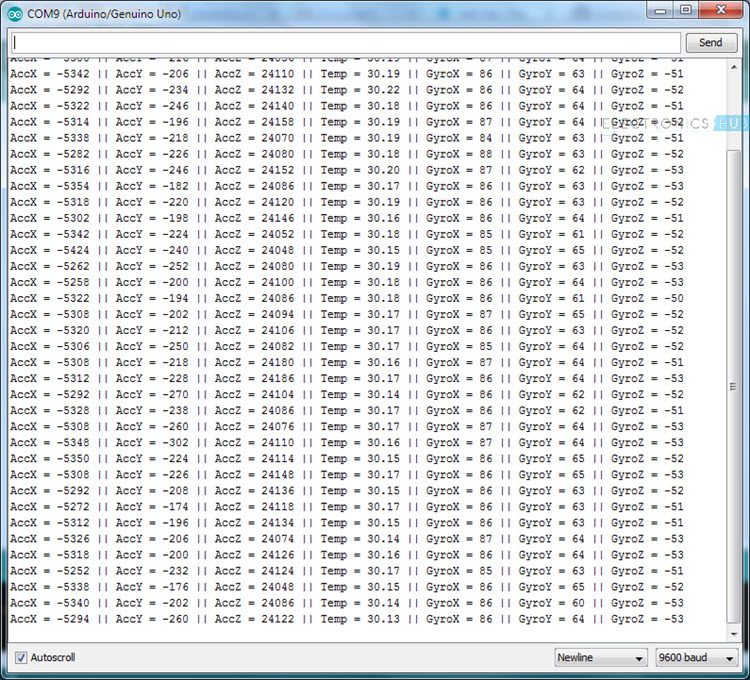
As you can see, reading the raw values from the MPU6050 sensor is easy but this data and we need to perform additional calculation on this data to get the Yaw, Pitch and Roll.
I’ve already mentioned that in MPU6050 sensor, there is a special processor called DMP or Digital Motion Processor that is embedded on the same chip as the accelerometer and gyro. The use of this DMP is that it can be programmed with a firmware for performing complex calculations on the data from the sensors.
But there is no clear documentation about the DMP from InvenSense’s side and as a result we are missing out on making fast calculations on the sensor’s data directly on the chip.
Jeff Rowberg and others has done an excellent job in reverse engineering the DMP related information from the I2C signal analysis.
Uploading the Code to Arduino and Testing MPU6050
Before uploading the code, we need to download two libraries for Arduino. They are I2Cdev and MPU6050. The download links and the official GitHub links are given below.
I2Cdev: DOWNLOAD I2CDEV LIBRARY
MPU6050: DOWNLOAD MPU6050 LIBRARY
Download the MPU6050 Library and extract the content by unzipping the downloaded file. You will get a folder with name “MPU6050”. Copy this folder and paste it in the libraries folder of Arduino.
In my case, it is located at “C:\Program Files (x86)\Arduino\libraries”. Do the same thing for I2Cdev library.
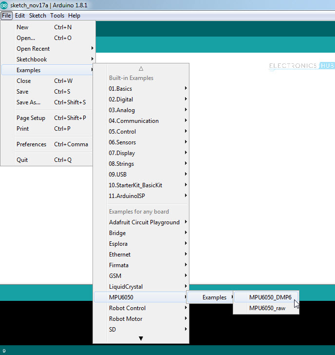
If everything goes well, open Arduino IDE and navigate through the following path: File -> Examples -> MPU6050 -> Examples -> MPU6050_DMP6 and open the example code MPU6050_DMP6.
Upload this code to Arduino (assuming that you have already made the connections as per the circuit diagram) and once the code is uploaded, open the serial terminal.
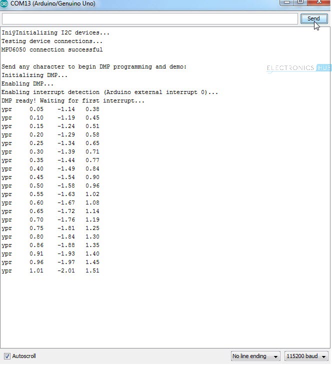
Set the baud rate in the serial terminal to 115200 and you will get the following text.
“Initializing DMP…
Initializing I2C devices…
Testing device connections…
MPU6050 connection successful
Send any character to begin DMP programming and demo:”
If you don’t get any data or still getting garbage data, just reset the Arduino. If you look at the last sentence, it say “Send any character to begin DMP programming and demo”. So, type any character like 1 or a in the serial monitor and send it. As soon as you hit enter, you can start seeing the Yaw, Pitch and Roll (ypr) values on the serial monitor.
NOTE: During this time, keep the MPU6050 on a stable and horizontal surface. Also, wait for 10 seconds for values from the MPU6050 to be stabilized.
3D Modeling in Processing based on values from Interfacing Arduino and MPU6050
In the next step of the project, we will take a look at 3D modeling the MPU6050 Sensor using Processing IDE, where you can view the 3D representation of the data from the sensor. Processing is a programming language and IDE that is developed for electronic arts and visual design. In fact, the Arduino IDE is also based on the Processing programming language.
To download the Processing IDE, visit this LINK. Download and Install Processing IDE using the given link.
After downloading the Processing IDE and installing it (simply unzip the contents from the downloaded zip file), you need to download a library for Processing called “Toxi”. You can download the Toxi Library from this LINK.
I’ve chosen the “toxiclibs-complete-0020” file. After downloading this file, extract the contents to a folder named “toxiclibs-complete-0020”.
Copy this folder and paste it in the libraries folder of the Processing. In my case, it was “C:\Users\Ravi\Documents\Processing\libraries”.
After copying the folder, you are now ready for 3D Modeling. First, you need to upload the previous Arduino code (MPU6050_DMP6) with few modifications.
Open the MPU6050_DMP6 (the example program which we uploaded earlier) in the Arduino IDE. Scroll down to the line that says the following.
Comment this line by adding double forward slash in front of it.
Also, find the line that says //#define OUTPUT_TEAPOT and uncomment it by removing the double forward slash. Now, you can upload the code. What we modified in the code is instead of sending the data to the serial terminal, we are forwarding it to the Processing IDE.
Now, open Processing IDE and click on File -> Open. Now, navigate to the folder where the MPU6050 library is installed for Arduino. Open the Processing example with name “MPUTeapot”.
In my case, the location for this example is C:\Program Files (x86)\Arduino\libraries\MPU6050\Examples\MPU6050_DMP6\Processing\MPUTeapot.
This program has a provision for automatically selecting the PORT Number to which Arduino is connected. The line in the code associated with this is
Another way to specify the PORT number of Arduino is to manually enter the COM Port number. To do this, comment the above line and uncomment the following line and replace the COM Port number with appropriate COM Port Number to which Arduino is connected to.
Before hitting the run button in Processing, make sure that the Serial Monitor of Arduino IDE is closed. Now, click on run button in the processing IDE. You will get a window with a plane like structure. Wait for 10 seconds before 3D modeling the MPU6050.
The movements made by the MPU6050 can be seen through the 3D Object on the screen.

5 Responses
I have installed the CODE. At reading the data through I am getting only one i.e. Temprature, someting like 36.00 and in other areas I am getting 1.
After going to Example MPU 6050, my PC is not compiling the sketch and showing ‘BOARD” arror. I am using Arduino Uno. I am stuck. Plesea help!
Sudhish Gokhale
Same with me bro did you found the answer
Hello. I’ve encountered an issue with the serial monitor display. it says: “DMP Initialization failed (code 1)” which is: initial memory load failed. Where exactly could be the problem?
it compiled for me with no errors. i have not tried it yet on ‘processing’
I have tried the code written above and it is printing -1 value for every reading.
Please help me out.