Here we are building a wireless FM transmitter which uses RF communication to transmit the medium or low power FM signal. The maximum range of transmission is around 2 km.
FM Transmitter Circuit Principle:
FM transmission is done by the process of audio pre amplification, modulation and then transmission. Here we have adapted the same formula by first amplifying the audio signal, generating a carrier signal using an oscillating and then modulating the carrier signal with the amplified audio signal. The amplification is done by an amplifier, whereas the modulation and carrier signal generation is done by an variable frequency oscillator circuit. The frequency is set at anywhere between the FM frequency range from 88MHz to 108MHz. The power of the FM signal from the oscillator is then amplified using a power amplifier to produce a low impedance output, matching that with the antenna.
Related Post: How TV Transmitter Circuit Works?
Circuit Diagram of 2 km FM Transmitter Circuit:
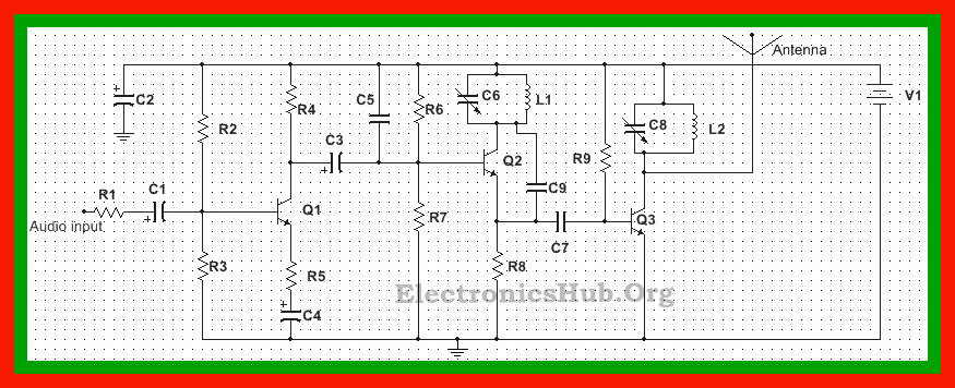
Circuit Components:
FM Transmitter Circuit Design:
Design of Audio Pre-amplifier:
Here we are designing a simple single stage common emitter amplifier as the pre-amplifier.
a) Selection of Vcc: Here we have selected the NPN Bipolar Junction Transistor, BC109. Since VCEO for this transistor is around 40V, we choose a much lesser Vcc, of about 9V.
b) Selection of Load Resistor, R4: To calculate the value of load resistor, we first need to calculate the quiescent collector current. Let us assume this value to be about 1mA. The collector voltage needs to be about half of Vcc. This gives the value of load resistor, R4 as : Vc/Iq = 4.5K. We select a 5K resistor for better operation.
c) Selection of Voltage Divider Resistors R2 and R3: To calculate the value of the voltage divider resistors, we need to calculate the bias current as well the voltage across the resistors. The bias current is approximated to be 10 times the base current. Now base current, Ib is equal to the collector current divided by the current gain, hfe. This gives the value of Ib to be 0.008mA. The bias current is thus 0.08mA.
The voltage across the base, Vb is assumed to be 0.7V more than the emitter voltage Ve. Now assume the emitter voltage to be 12% of Vcc, i.e. 1.08V. This gives Vb to be 1.78V.
Thus, R2 = Vb/Ibias = 22.25K. Here we select a 22K resistor.
R3= (Vcc-Vb/Ibias = 90.1K. Here we select a 90K resistor.
d) Selection of Emitter Resistor R5: The value of R5 is given by Ve/Ie, where Ie is the emitter current and is approximately equal to the collector current. This gives R5 = (Ve/Ie) = 540 Ohms. Here we select a 500Ohms resistor. It serves the purpose of bypassing the emitter current.
e) Selection of coupling capacitor, C1: Here this capacitor serves the purpose of modulating the current going through the transistor. A large value indicates low frequency (bass), whereas a lesser value increases treble (higher frequency). Here we select a value of 5 uF.
f) Selection of Microphone Resistor R1: The purpose of this resistor is to limit the current through the microphone, which should be less than the maximum current a microphone can handle. Let us assume the current through microphone to be 0.4mA. This gives the value of Rm = (Vcc-Vb)/0.4 = 18.05K. Here we select a 18K resistor.
g) Selection of Bypass Capacitor, C4: Here we select an electrolyte capacitor of 15 uF, which bypasses the DC signal.
[Also Read:How to build Adjustable Timer]
Design of Oscillator Circuit:
a) Selection of tank circuit components – L1 and C6: We know the frequency of oscillations is given by
f = 1/(2∏√LC)
Here we require a frequency between 88 MHz to 100 MHz. Let us select a 0.2uH inductor. This gives value of C6 to be around 12pF. Here we select a variable capacitor in the range 5 to 20pF.
b) Selection of Tank Capacitor, C9: This capacitor serves the purpose of keeping the tank circuit to vibrate. Since here we are using BJT 2N222, we prefer the value of C9 between 4 to 10 pF. Let us select a 5 pF capacitor.
c) Selection of bias resistors R6 and R7: Using the same method for calculation of bias resistors, as in the preamplifier design, we select the values of bias resistors R6 and R7 to be 9 K and 40 K respectively.
d) Selection of coupling capacitor, C3: Here we select electrolyte capacitors of about 0.01 uF as the coupling capacitor.
e) Selection of emitter resistor, R8: Using the same calculations as for the amplifier circuit, we get the value of emitter resistor to be around 1K.
Design of Power Amplifier Circuit:
Since we require a low power output, we prefer using a class A power amplifier with LC tank circuit at the output. The values of the tank circuit components are same as that in oscillator circuit. Here we select the biasing resistor to be about 20 K and coupling capacitor of about 10 pF.
Selection of Antenna:
Since the range is about 2 km, we can prepare an antenna using a stick antenna or a wire of 30 inches approximately which would be about 1/4th of the transmitting wavelength.
Theory Behind FM Transmitter Circuit:
Audio signal from the microphone is very low level signal, of the order of mill volts. This extremely small voltage needs to be first amplified. A common emitter configuration of a bipolar transistor, biased to operate in class A region, produces an amplified inverted signal.
Another important aspect of this circuit is the colpitt oscillator circuit. This is a LC oscillator where energy moves back and forth between the inductor and capacitor forming oscillations. It is mainly used for RF application.
When this oscillator is given a voltage input, the output signal is a mixture of the input signal and the oscillating output signal, producing a modulated signal. In other words, the frequency of the oscillator generated circuit varies with the application of an input signal, producing a frequency modulated signal.
How to Operate FM Transmitter Circuit?
Audio input from the microphone or any other device is first amplified using the common emitter configuration of BC109. This amplified signal is then given to the oscillator circuit through the coupling capacitor. The oscillator circuit generates a signal with a frequency determined by the value of the variable capacitor. The output signal from the emitter of the transistor is coupled to the input of the power amplifier transistor using the coupling capacitor. As this signal is amplified, the variable capacitor in the power amplifier section tends to maintain an output matching with that of the oscillator. The amplified RF signal is then transmitted using antenna.
Applications of FM Transmitter Circuit:
This circuit can be used at any place to transmit audio signals using FM transmission, especially at institutions and organizations.
Limitations:
This circuit is for educational purposes and may require more practical approach.
Related Post: FM Bugger Circuit

55 Responses
how i made L1 and L2 ?
They are available in market by built.
C4 & R5 it should be parallel, not serial.
can u make the audio input a 3.5mm jack female
i am doing my mini projct with this circuit,,will it works correctly?if any corrections required plz infrm me,,its lil urgent fr me,,cn u?
did you do the project on this ckt..? did it work..?
hi preetha how to increase the transmit range
which power transistor i have to take
iam doing Fm transmitter in what frequency it will transmit .only in tat part we r stuck plz admin say in which freq
what about the voltage rating of the capacitors and if it did not work or one of the transistor start getting hot what should i do.
Hi,
Can you provide some more info on the components? Like C1 = 5uF but what about volts? Same with R1, it is 18K but what about watts? Is it 1/4 watts? When I go to an online site to buy these components I see additional Volts and Watts, not sure what to choose.
I am new to making electronic circuits so my questions might sound vague. Looking forward to some help.
Thanks
all R/k you can use 1/4 watt.
How to make L1&L2 using copper wire.(What my question exactly is that that, how many turns do i take and what should be the diameter of the coil.)Please help.
What should be the diameter of the coil L1&L2 and how many rounds should i take on the rod of that diameter.Please help.
Please, what is the value of Q1 and Q2
i dint find any of the range of L1 and L2…..pls help me….
0.01uF, Electrolyte i think this is ceramic capacitor not electrolyte ?
Hi, what transistors do I use as Q1 Q2 and Q3??
search for high frequency transistors, you can use bf199
What about Q3?
what to be used as Q3 ??
How to change the frequency….means a desired frequency
and how to increase the range…
which transistors have been used??
Can u please tell me what will be the tune (carrier) frequency of this circuit??
You can calculate using formula 1/2π√LC for L1,C6
We use some old radio parts
What is value of transistot Q3???
Which type of antenna should I use for smaller distances??
i am making mini projct with this circuit will it works correctly?if any corrections required please inform me. As soon as possible….
And what’s types of transistor (Q2 & Q3) are use here ..
Can you make L1&L2 if yes …
How??????
Please reply fast
how can i connect the audio input in this circuit?????
plz what about Q1,Q2&Q3????
Hi.. Please tell me q1 q2 q3 and l1 l2
I want no how to make a transmitter.
???? Hy give me your Q1,2,3,transistor name plz……
Transistors names plzz….
Q1 bc109 and Q2 2n222 and q3 idk..
please provide us the value of transistor Q3…..the values of Q1 and Q2 are given as BC109 and 2N222 or 2N3904…
what is the value of other two transistors Q1 and Q2
can u specify the transistors Q1,Q2,Q3? which one u have used in this circuit?
how to calculate the output impedance of that circuit?
How can we add audio input from mp3 prayer to this circuit?
R2 and R3 values should be interchanged i.e R2=90K and R3=22K. The formula used is also exactly reverse.
what is the bandwidth of this transmitter
what frequency it transmits?
I am thinking of doing this project. Please tell me the values of Q1, Q2 and Q3. Also suggest any other correction requited. Please reply fast..
WHAT IS THE GAIN AT EACH STAGE?
hi, I am working on a transmitter project in my school and I want to confirm if this circuit has been tested working before proceeding to get the parts.
pls your urgent reply will be really appreciated.
thanks
We have not tested this circuit.This circuit is designed based on theory
What the value of q3
Which type of resistor and capacitors is used in 2 km fm range transmitter.Please send me the picture of resistor and capacitor picture
name of transistor
how much power will be consumed for 2 km transmission ?
how I receive this RF signal. which receiver circuit I use?
How can i Check that this circuit works? or which software will help me simulate this?
What is the value of C9?