In this project, I will explain you how to design a Simple IR Audio Link circuit, which is used to transmit audio signals wirelessly. This IR audio link is able transmit audio signals for short distances. The audio signal which is to be transmitted is applied at the base of the transistor in Transmitter section. An 8 speaker or head phone is connected at the receiver section to listen to the transmitted signal.
Introduction
Wireless Audio is already a technically advanced field where Bluetooth and RF Communications are the main technologies (although most commercial audio equipment works with Bluetooth). Designing a simple IR Audio Link Circuit would not be beneficial when compared to the existing technologies but it surely will be a learning experience about wireless audio transfer.
The reason for not being beneficial is the fact that unlike Bluetooth, IR is line-of-sight communication i.e. both the transmitter and receiver must always face each other without any obstacles. Also, the range may not the as large as that of a typical Bluetooth Wireless Audio.
None the less, for the purpose of understanding, let me design a simple IR Audio Link circuit using easily available components.
Simple IR Audio Transmitter and Receiver Circuit Principle
The main principle in this circuit is IR communication. Infrared (IR) is used only for line – of – sight communications over low range. In electromagnetic spectrum Infrared rays are rays are having the wavelengths longer than the wavelengths of visible light. These Infrared rays are not visible to the human eye, but we can view these IR rays through the digital camera.
A typical IR communication system includes infrared source such as Infrared lasers or LEDs with specific wavelengths. The transmission mediums used for IR communication is vacuum, atmosphere and optical fibers. Finally in IR communication, to detect the IR rays, we will use photo diodes or photo transistors.
The output signal from this detectors is very small and might not be able to drive the speakers. Hence, we will use a simple amplifier to amplify the signal. This amplified signal can be able to drive the speakers.
IR Audio Transmitter and Receiver Circuit Diagram

Components Required
Transmitter Section
- 9V Battery
- Resistor – 1KΩ X 2
- IR Transmitters (IR LEDs) – 2
- BC548 NPN Transistor
- Connecting wires
- Breadboard
Receiver Section
- Photo Diode
- Resistor – 100KΩ
- POT – 100KΩ
- Capacitors – 0.1µF X 2, 10µF, 47µF
- LM386 Audio Amplifier
- Connecting wires
- 8Ω Speaker
- 9V Battery
- Breadboard
Simple IR Audio Link Circuit Design
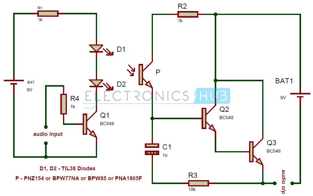
The IR audio link circuit is divided two parts: one is the transmitter section and the other is the receiver section. The transmitter section works with 9V battery. Here, the audio signal input is applied at the base of the Q1 via 1KΩ resistor.
Here, the transistor Q1 is used to drive the IR LEDs D1 and D2. The input audio signal is modulated to Infrared signals transmitted.
The transmitted Infrared signals are received by the photo Diode. The audio signal is now converter into electrical signal and is further passed to LM386.
LM386 is a simple Audio Power Amplifier IC with a maximum output power of approximately 1W. It can drive both 4Ω and 8Ω speakers and in this circuit, I have used a mini 8Ω Speaker.
In this circuit, to power the transmitter and receiver sections, I have used 9V batteries. Instead of Photo Diode, you can also use a Photo Transistor like BPW77NA, BPW85, PNA1605F or PNZ154 in the receiver section.
NOTE: In case you are using a Photo Transistor, the circuit at the receiver end changes to the following.
How to Operate IR Audio Transmitter and Receiver Circuit?
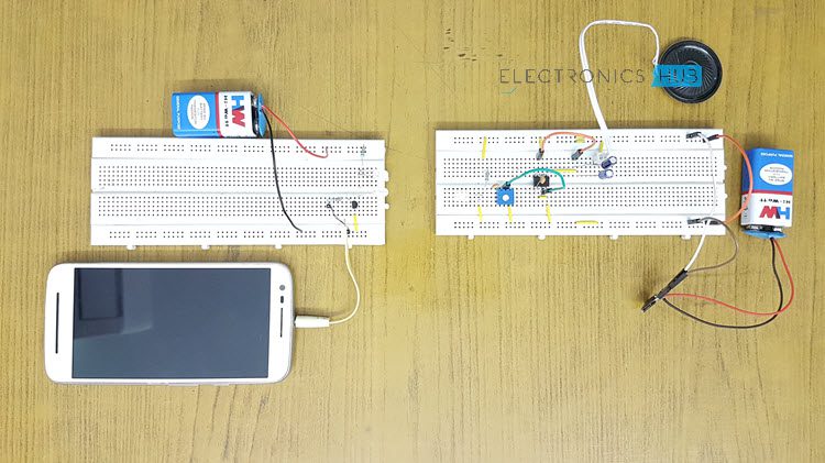
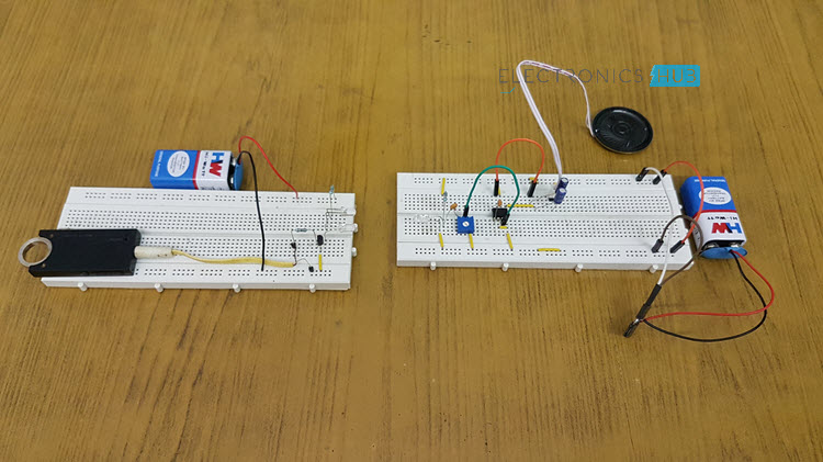
- Initially give transmitter and receiver the connections separately as per the circuit diagram
- Apply power to the both transmitter and receiver sections using two 9V batteries.
- Connect an 8 Ω speaker at the output of LM386 Audio Amplifier IC.
- Make sure that distance between Transmitter and receiver sections is below 30cm.
- Apply the audio signal at transmitter section using a mobile phone or a music player. Now you can listen the sound from speaker.
- Disconnect the batteries from transmitter and receiver
Simple IR Audio Link Circuit Applications
- Used in audio communications to transfer the audio signal from one place to other.
- Used in short range communications.
Simple IR Audio Link Circuit Limitations
- This IR audio link circuit works only for short distances
- This circuit is not very practical in the sense that there exists a lot of noise and may require some changes to implement it more efficiently.

8 Responses
I conducted this experiment. A small piece of advice is that the transistors need to biased using a voltage divider network in order to improve the stability. This configuration is highly unstable and the output starts to distort enormously in just a few minutes.
How to provide audio input??. Have you done this circuit??. Did that worked??
Please reply
As Soumya Sambeet Mohapatra said that this circuit is highly unstable, we burnt our transistors twice doing it.
can anyone please give schematic of this circuit with biased voltage division for stability
please it is very urgent.
We need it as soon as possible
kya kio iska ckt daigram aur components ka list bhejega jiska output aya hain plzz.
so is good circuit .it’s used in short range.
is good
which type of modulation scheme is used in this circuit
Can i use RF instead of ligth?