Have you ever thought of transmitting audio and video signals? Here is the simple circuit that amplifies and transmits audio, video signals. These are transmitted in very high frequency band (VHF).
TV Transmitter Circuit Principle:
The main principle of this circuit is to transmit the audio and video signals. Here audio signals are frequency modulated and video signals are PAL modulated. These modulated signals are applied for the antenna.
Also get an idea about How FM Radio Transmitter Circuit Works?
TV Transmitter Circuit Diagram:
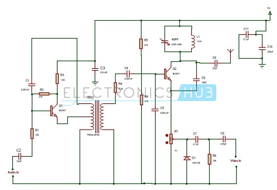
The circuit consists of following components:
- BC547 transistor.
- Signal diode (1N4148).
- Resistors.
- Capacitors.
- Radio frequency transformer.
- Antenna.
- Variable capacitor.
- Variable resistor.
Read this interesting concept: TV Remote Jammer Circuit using 555 Timer IC
TV Transmitter Circuit Design:
The TV transmitter circuit design is explained below.
The audio signal is applied to the base of the transistor through a resistor and capacitor of 10Kohms and 10uf respectively. Emitter of the transistor is connected to the radio frequency transformer. The audio signal here is pre-amplified by the transistor.
Radio frequency transformers are used for maximum power transfer. They have two windings Primary and secondary. The voltage is applied at the primary winding and due to mutual inductance some voltage is induced in the secondary winding of the transformer. Hence voltage can be transferred from one circuit to another circuit. Here in this circuit, a transformer with an inbuilt capacitor is used.
Signal diode is a diode which allows the current to flow only in one direction. They pass small currents upto 100mA and process the information in the electrical signals. They are used widely in signal processing. Here signal diode is used for video modulation.
The audio input is connected to the base of the transistor through a resistor and capacitor in series. A LC tank circuit is connected to the collector terminal of the transistor .This tank circuit produces the carrier frequency for modulation .The tank circuit consists of a variable capacitor and a resistor in parallel.
Video input signal is applied to the transistor through the variable resistor of 1kohms. It is fed to the pot through a capacitor of 0.1uf and a signal diode in parallel to it.
The modulated signals are fed to the antenna. Antenna is required to transmit the signal. Antenna takes the electrical signal and converts them into an electromagnetic radiation. This radiation is emitted by the antenna.
How to Operate TV Transmitter Circuit?
- Initially connect the circuit as shown in the circuit diagram.
- Apply a voltage of 12v through a battery to the circuit.
- Now the audio input is applied to the base of the transistor.
- The transistor pre amplifies the audio signal and is applied to the RF transformer.
- Video signal is applied at the input of the video.
- Here RF transformer applies the audio signals to the transistor Q2.
- The transistor Q2 modulates the audio , video signals and transmits them to the antenna.
- The carrier frequency required for modulation is produced by the tank circuit.
- Thus the modulated wave is transmitted by the antenna and this circuit works with VHF band somewhat between 50-210 MHZ.
TV Transmitter Circuit Applications:
- This is used in broadcasting applications.
- This circuit can transmit audio and video signals from DVD, videogames, etc.
- The circuit can be used in surveillance cameras.
Limitations of the Circuit:
- The transmitter circuit is compatible with PALB and PALG systems.
- To get optimum performance, one should adjust the value of C8.

12 Responses
nice project you made, thanks for sharing.
did u perform that project?
Have u done this project Mr.vissu ???
If u done this I have some doubts…please give me suggestions …”uchandu.svct@gmail.com” this is my id …so waiting for it reply
Very useful this wap site
if I use this tv transmitter where do I expect to receive the signal because I want the transmitted data to be accessed by me and no one else?
i want to know where the data is transmitted? do I need to build a receiver ?
it can be received on ur tv sets
serious i don’t believer this is possible with circuit you have provided
please can you add video demonstration of that work
Nice project,how to increese the radius?give us the power amp for that circuits
Very Nice project For Audio Video transmission. What is the Range Of this transmitter
I like it
Can I give video signal directly from camera??