Logic gates are basically are group of three basic logic gates specifically called as NOT , AND and OR gate. All the gates have their own identical logical function. By the combination of these gates, we can obtain any Boolean or logical functions or logical function.
Related Post: Design of Basic Logic Gates using NAND Gate
Truth Tables of Basic Logic Gates:
We first need to get aware with the working of each and every gate before knowing the conversion.
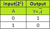
1. NOT Gate:
It is the most simple type of the digital logical circuit. These gate is a two terminal device one is for the input and another is for the output and the input which is given to NOT gate can only be a binary number i.e. it can either be a 0 or can be 1. The output of the NOR gate is always opposite of the input , which means that if we give logic 1 at the input of the gate then the output will be logic 0 and vice versa. The number of stages that can be obtained can be calculated by 2n (where n is the number of input) . In these case we have only one input so the number of stages that can be obtain is either 0 or 1 (21).
Truth table of NOT gate is shown below-
2. AND Gate:
AND gate is a three terminal device in which two terminal is for the input and one is for the output purpose. The working of the logic gate is such that we obtain binary 1 at the output if and only if both the input is at the binary1. In the case if any of the input is at the binary 0 state the output that we get will be binary 0.AND gate truth table is shown below-
Number of stage that can obtain = 2n (n is the number of the input terminals)
So, 2n = 22 = 4.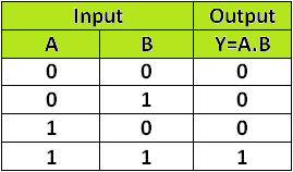
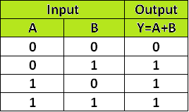
3. OR Gate:
OR gate is another basic logic gate like AND gate it as two input and one output. The operation of gate is such that output of gate is binary 1 if any of the input is binary low and we will receive logic zero only when both the inputs are low. Truth table of OR gate are as follows-
Number of stage possible = 2n =22 = 4.
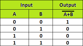
4. NOR Gate:
The word NOR gate is just an short form of the NOT and OR gate combination. Hence a NOR gate is made up from a OR gate which is followed by an inverter. If all the inputs is at the binary low state i.e. at 0 then the output received will be at the binary high state i.e. at the 1 and in case of any input of both the input at binary high the output will be binary low.
The expression as well as truth table of the NOR is been shown below –
Transformation of NOR Gate into Basic Logic Gates:
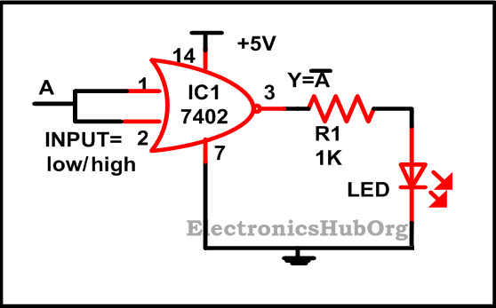
1. Construction of NOT Gate using NOR Gate:
For the NOT gate both the input terminal has been shorted which you can see in the figure drawn above since NOT has only one input. Now when we give binary high signal i.e. 1 at the input the output that we get will be binary low i.e. 0 which you can find out from the truth table of the NOR gate. IC 7402 is been used by us which is a quad two input NOR gate.
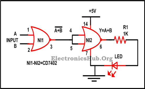
2. Construction of OR Gate using NOR Gate:
3. Construction of AND Gate using NOR Gate:
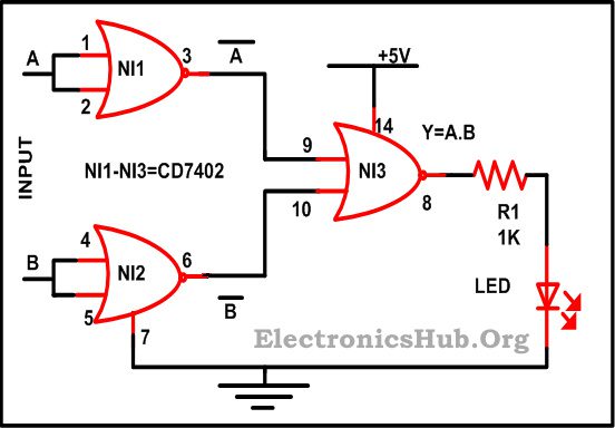
For getting familiar with these it is important that one should have knowledge about the De Morgan’s theorem – According to the theorem the sum of the complement is equal to the product of the complement.
(A+B)‾ = A‾ . B‾ – EQ 1
From the figure shown above, Two NOR gate is been used by us and we short the input terminal of each gate so the output we will obtain as
= A‾ + B‾
Now these output is again given as an input of the another NOR gate and the output which we will get as
= (A‾ + B‾)‾
=A‾ ‾ + B‾ ‾
= A.B
Required Components:
- IC
- CD7402 – 1
- R1 (1K) – 1
- LED – 1

4 Responses
Can we convert OR gate into AnD Gate
gap
Useful information thanxxx
It’s very useful thank you so much can u give any other example