A Tilt Sensor or a Tilt Switch is a component that detects orientation of an object. One of the best example for the application of a tilt sensor is its use in aircrafts.
The horizontal and vertical orientation or inclination of the airplane will be provided by the tilt sensor to on board computers. This information is provided to the pilot for safe travelling.
A simple tilt sensor is basically a switch that will turn ON or OFF based angle or orientation of the sensor. Such sensor is useful for single axis tilt detection.
In this project, the basic functioning of a tilt sensor in determining the orientation is demonstrated.
How To Make A Tilt Sensor With Arduino?
Circuit Diagram
 Components Required

- Arduino UNO [Buy Here]
- Tilt Sensor
- LED
- Resistor
- Buzzer
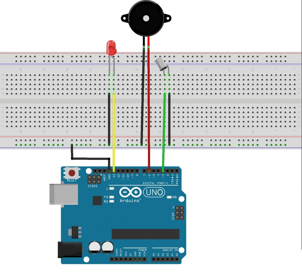
Circuit Design of Arduino Tilt Sensor
As mentioned earlier, a tilt sensor is basically a switch. One end or terminal of the tilt sensor is connected to any of the digital I/O pins of Arduino.
In this project, it is connected to pin 3 of Arduino. The other terminal of the sensor is connected to ground.
A buzzer and an LED are used to indicate the detection of the tilt by Arduino. The buzzer is controlled by the PWM output of the Arduino to generate different tones.
Hence, positive terminal of the buzzer is connected to any of the PWM pins of the Arduino. In this demonstration, it is connected to pin 6. The other terminal of the buzzer is connected to ground.
LED is also used to indicate the tilt action. As the output current from Arduino is only 20mA, we are connecting the LED directly to Arduino without any current limiting resistor.
It is advised to use a current limiting resistor just to be safe. Anode of the LED is connected to pin 13 of the Arduino while the cathode is connected to ground.
Working of Arduino Tilt Sensor
A Tilt sensor is similar to a normal switch except that the current flows through it only when it is tilted at a certain angle. Hence, a tilt sensor is used to detect the tilt or orientation of an object.
There are different types of tilt sensors. For a simple one axes orientation, a tilt switch with accurate angle of orientation can be used. An accelerometer based 3- axis tilt sensor is used to detect full motion in three axes.
In this project, we used a single axes tilt sensor. There are two technologies that are used in the implementation of Tilt Sensors: Mercury based and Roller Ball based. Older tilt sensors are made of mercury.
A blob of mercury is placed in a small glass tube with two metal contacts coming out. When the sensor is held upright, the mercury will make contact with both the terminals and the switch is closed.
When the sensor is tilted in either direction, the mercury goes off contact with the terminals and the switch is open.
In roller ball based tilt sensors, one or two metal balls are used to close or open the switch. When the sensor is positioned upright, the metal ball makes contact with both the terminals and closes the switch.
When the orientation of the sensor is changed i.e. tilted at an angle, the metal ball loses contact with the terminals and the switch is open.
The advantage of mercury based tilt sensor is that there is no chance of de-bouncing. But due to the toxic nature of mercury, the usage of such type of tilt sensors is reduced.
Irrespective of the type of the sensor used, the best way to test the tilt sensor is by using the following circuit. It consists of a tilt sensor, an LED, a current limiting resistor and a power source like battery.
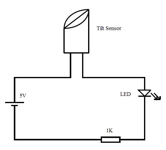
When the sensor is held upright, the circuit is closed. Current flows through the LED and it glows. When the orientation of the sensor is changed, the circuit is open and the LED is turned off.
Another simple way to test the tilt sensor is using a multimeter. The multimeter is set to continuity mode and the terminals of multimeter are connected to tilt sensor. The angle at which the switch opens and closes can be determined by this test.
In this project, an Arduino will sense the tilt of the sensor and triggers a buzzer and an LED. The code for Arduino is written and uploaded to the board.
When the tilt of the sensor is detected, the buzzer and LED are triggered by Arduino.
Code
NOTE
- The working of a simple tilt sensor is demonstrated in this project.
- Tilt sensors can be used in security systems, where the orientation of the object is used as the security measure.
- Tilt sensors are often used in gaming consoles and mobile phones.
- They are used in navigation systems of boats, airplanes etc., to determine the pitch and roll.

6 Responses
It is a very nice project.
How to check
upload the code to your arduino and check
Hi, first,
thank you for posting this. I am new to all this, and I am learning bit by bit.
I have uploaded the code, and everything is connected as it should but it does nothing. and I tried with 2 different boars. Any suggestions? Thank you
Fernando
Correction:
The led turns on only when the Tilt switch is connected to pin#2. Not #3. Not sure why.
But the Buzzer does not work and I cannot make it work. Any Idea why?
Thank you
My light is already lit up when I upload the code to the board. And the LED turns off when it is tilted so its switched around. How do I fix this?