A Rotary Encoder is an electromechanical device that converts angular movement of the shaft to analog or digital code.
In this project, the working of Rotary Encoder is explained with the help of Arduino. The following sections are dived into introduction to rotary encoders, circuit and working.
Rotary Encoder With Arduino
Circuit Diagram
Hardware Required
- Rotary Encoder
- Arduino UNO
- LCD Display
Introduction to Rotary Encoders
A Rotary Encoder is an input device that provides the information about the direction and amount of rotation of the knob. There is a select switch associated with the rotary encoders that can be activated by pushing the knob.
The commonly used rotary encoder is an incremental rotary encoder. This type provides an instantaneous result about the rotating shaft by generating two square wave outputs that are 90 degrees out of phase with each other.
A rotary encoder has to coding pins A and B produce either High or Low output depending on the rotation and direction of the shaft.
The basic function of a rotary encoder can be explained by considering it as a combination of two switches that close or open due to rotation of the shaft.
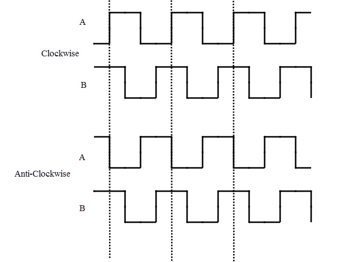
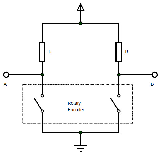 As the shaft rotates, the switches are closed and opened in a pattern. If the outputs are treated as binary, then for clock wise rotation, the outputs at A and B will be 00, 01, 11 and 10.
For anticlockwise or counter clockwise rotation, the outputs will be 10, 11, 01 and 00. The waveform of the pulses in both directions of rotation is shown below.
To test the sequence, the output pins of the rotary encoder are connected to two LEDs as shown in the following circuit.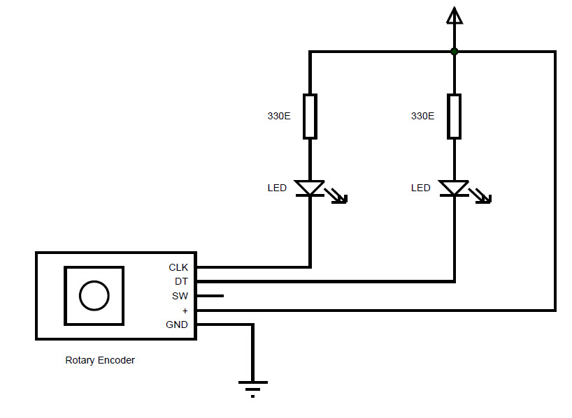
When the knob of the rotary encoder is rotated in clockwise or anti clockwise directions, the LEDs light up as per the above mentioned sequence.
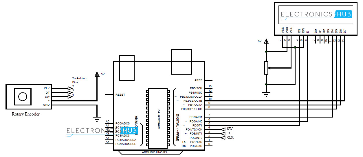
Circuit design of Rotary Encoder with Arduino
Rotary Encoder consists of five pins: two coding pins A and B (or CLK and DT), one pin for switch and two power supply pins for Vcc and GND.
The two coding pins and the switch pin provide digital signals. They are connected to pins 2, 3 and 4 of Arduino.
To display the objects of the menu, a 20X4 LCD display is used. The connections are similar to that of 16X2 LCD. RS and E of LCD are connected to pins 5 and 6 of Arduino.
The data pins i.e. D4 – D7 (pins 11 – 14) of LCD are connected to pins 7 – 10 of Arduino.
Working
Rotary Encoders provide infinite rotation in either direction with a select button (pushing the knob). Such unique functionality can be used in “menu” selection applications, where the rotation of shaft in either direction will allow us to browse the contents of the menu and push of the button will allow us to select the highlighted menu content.
In this project, the working of rotary encoder as a menu selector is explained with the help of Arduino and LCD. The working of the circuit is as follows.
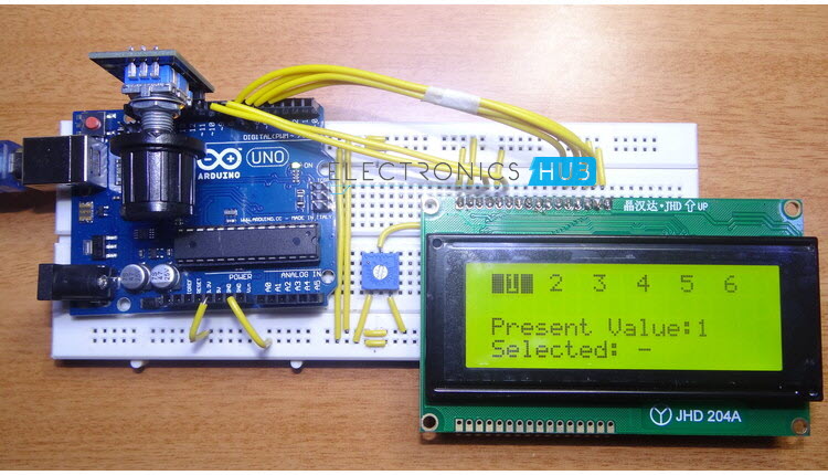
The code for Arduino is written as per the application and uploaded to Arduino. On power up, the LCD displays the list of values horizontally.
By rotating the shaft of the rotary encoder in clockwise direction, the menus items will change from left to right with each item being highlighted for every turn of the knob.
Once the last item is reached, further rotation will not result in any action but the last item will be highlighted.
If the knob is rotated in anti-clockwise direction, the menus items will be highlighted in reverse direction. The highlighted item will be displayed below the list of items.
If we want to select any highlighted item, the button of the rotary encoder is pushed. This is shown as the selected item and the selected item stays that way until the next item is selected.
Code
NOTE
- The working of a Rotary Encoder is explained in this project with the help of normal switching operation and as menu selector using Arduino.
- Can be implemented as a selector switch for a menu with multiple levels of hierarchy in each submenu.
- If the levels of hierarchy in menu contents are more, then the concept of Interrupts must be used in Arduino.
- Rotary Encoders can be used in precision control of servo and stepper motors.

6 Responses
Hey,
could you send me the code?
Thnaks 🙂
Hey, check out the article end, we have added code. Thanks
Hi,
can you please tell me where to find RotaryEncoder.h library ! as i think its a custom library.
Hi, can you please tell me where to find RotaryEncoder.h library .Thanks
rotary encoder on ebay right know
Thanks for shering this.
I built it and its workinf fine. I’d like to use this menu in my project but I need some help.
I need to change two or three values inside each of the menu items.
For example if selected menu item is 1, I need to edit value of variable a and b, if selected is menu 2, I need to change variable c, d and e. values of those variables would be between 0 and 250.
What would you recommend as the easiest way to that?
I understand this article is 2 years old, but I hope you can help me.
P.S. On the connection diagram encoder is connected to pins 2, 3 and 4 but in the code corresponding pins are 10, 11 and 12. Not a big deal but might be confusing.
All the best!