In this tutorial, we interface an I2C Serial EEPROM IC AT24C256 with Arduino. First, we will see a little bit about the AT24 Series EEPROMs, the pinout and pin description of AT24C256, write a couple of functions to READ and WRITE data from/to the EEPROM and finally understand how the Arduino AT24C256 EEPROM Interface works.

Interface AT24C256 I2C EEPROM with Arduino
EEPROM, which is short for Electrically Erasable Programmable Read Only Memory, is a type of non-volatile memory which retains its contents even after the power is turned off.
There are two types of EEPROM with respect to the physical location. One is Internal EEPROM, which is embedded into the Microcontroller and the other is External EEPROM, which is in the form of an IC and must be connected to a Microcontroller through a Serial Interface (like I2C or SPI).
I already discussed on how to access the Arduino’s Internal EEPROM in an earlier tutorial. For more information about EEPROM (and its history), volatile and non-volatile memory and reading and writing to Internal EEPROM of Arduino, check out “ARDUINO EEPROM TUTORIAL”.
Internal EEPROMs are often limited in size (usually a couple of kB) but are significantly fast as they are on the same silicon as the processor in the MCU. If you take Arduino UNO as an example, the ATmega328P MCU (which is the Microcontroller on UNO) has only 1 kB of EEPROM.
This is where External EEPROM ICs come into play. You can get capacities up to 256 kB (or more) and can be easily interfaced either through I2C or SPI.
A Brief Note of AT24C256
If we talk about Serial EEPROM ICs, then the Atmel’s (now Microchip) AT24 and AT25 series are very popular. The AT24 Series are I2C EEPROMs while the AT25 Series are SPI EEPROM ICs.
For this project, I chose the AT24C256 IC, which is a 256 kbit EEPROM. This translates to 2,62,144 bits or 32,768 Bytes (32 kB).
It is an 8-pin IC available in 8-lead SOIC, 8-lead TSSOP, 8-pad UDFN or 8-ball VFBGA packages. The 8-lead SOIC is popular in arduino modules.
Pin Diagram
The following image shows the pin diagram of AT24C256 EEPROM IC.
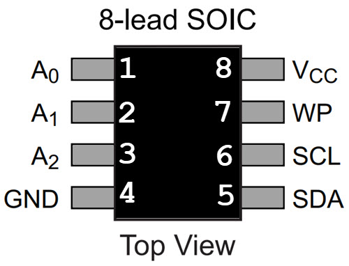
Pin Description
|
Number |
Pin |
Function |
|
1 |
A0 | Address Input |
| 2 | A1 |
Address Input |
|
3 |
A2 | Address Input |
| 4 | GND |
Ground |
|
5 |
SDA | Serial Data |
| 6 | SCL |
Serial Clock |
|
7 |
WP | Write Protect |
| 8 | VCC |
Power Supply |
Arduino AT24C256 EEPROM Interface
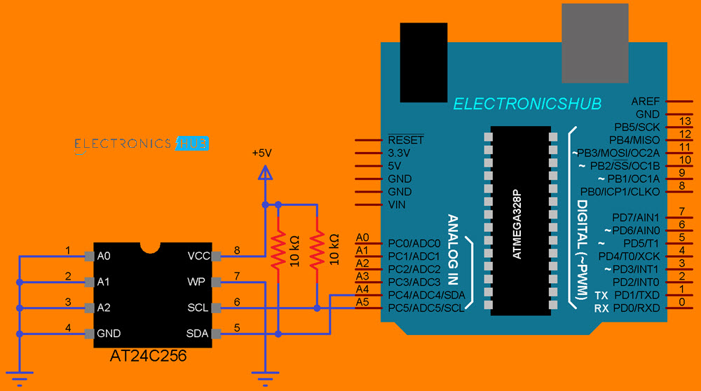
Let us now proceed with interfacing AT24C256 EEPROM IC with Arduino UNO. First thing to note is that AT24C256 (or any other AT24 Series EEPROM) communicates over I2C Interface. So, use the Analog Pins A4 (SDA) and A5 (SCL) for I2C Communication.
Since it is an I2C Communication, we need pull-up resistors for the SDA and SCL lines. I used a couple of 10 kΩ Resistors as pull-ups. Rest of the connections are very simple and are shown in the circuit diagram.
Next is the device address. If you take a look at the datasheet, you get a diagram on how to use the Address Input pins to configure the Device Address of the IC.
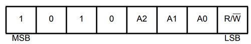
The sequence “1010” for first four MSBs is mandatory for all I2C EEPROMs from Atmel. The next three bits i.e., A2, A1 and A0 allow you to connect up to 8 devices on the same I2C Bus.
As we are using only one AT24C256 IC, the three Address Input pins A2, A1 and A0 are connected to ground to make their corresponding values in the Device Address as “000”.
The last bit (LSB) is the Read or Write operation selection bit. If this is ‘1’, then the Read operation is selected and if this bit is ‘0’, then the Write operation is selected.
NOTE: We can ignore the LSB of the device address while writing the code as Arduino Wire (and internal TwoWire) library takes care of it depending on the operation. So, we can declare the address as “0x50”.
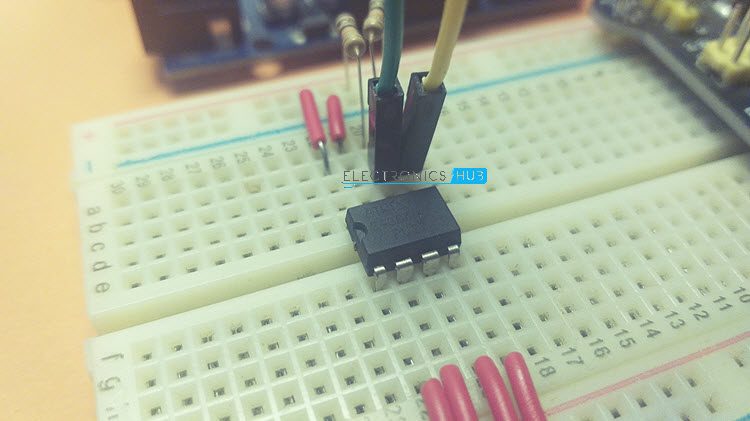
NOTE: My AT24C256 EEPROM IC got damaged while shipping. I will be using an older AT24C04 IC, which has a capacity of 4 kb (4096 bits or 512 B), for demonstration. The circuit remains the same as they both are I2C EEPROMS with same pins and code needs very small modifications.
Components Required
- Arduino UNO
- AT24C256 EEPROM IC
- 2 x 10 kΩ Resistor
- Connecting Wires
- Breadboard
- Breadboard Power Supply (optional)
Circuit Diagram
The following image shows the circuit diagram of Arduino AT24C256 EEPROM Interface.
Code
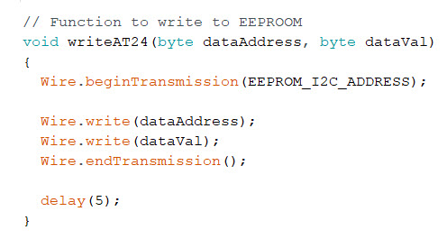
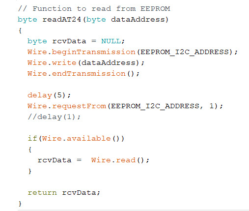
For writing the code, you need not download any additional libraries as we are going to use only the “Wire” library (which comes with Arduino IDE). Instead of using a dedicated library, I decided to write two functions for Read and Write operations of AT24C256 using the Wire library.
Write a Byte to EEPROM
Read a Byte from EEPROM
Code
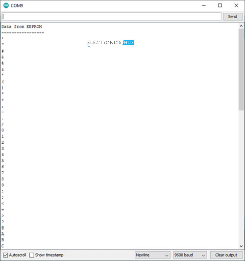
To demonstrate the working of Arduino and external EEPROM IC Interface, I wrote small code which stores the ASCII values from 33 (‘!’) to 126 (‘~’) using the write function.
After storing them in the EEPROM, I read them using the read function and printed the characters on Serial Monitor.
Conclusion
A simple tutorial on how to interface AT24C256 EEPROM IC with Arduino. If you understand how the Arduino AT24C256 EEPROM Interface works, then you can implement any data acquisition applications.
