In Direct Current (DC), the flow of electric charge is unidirectional. In DC, the voltage and current maintain a constant polarity and direction. The source of direct current is the battery. On the other hand, in Alternating Current (AC), the flow of electric charge reverses direction periodically. In AC, the voltage changes polarity from positive to negative and vice versa over a period of time. This change in the polarity of the voltage is because of the change in the direction of current.AC is the supply used to power up the households, offices, industries, etc. Even though sine wave is the most common form of AC supply, some applications use different wave forms like triangular wave, square wave and sawtooth wave.
The most common form of AC supply is sinusoidal wave. The mathematical function describing a typical AC voltage is
V (t) = VMax sin ωt.
V (t) is the voltage in the function of time. The voltage changes with time.
t is the variable time in seconds.
VMax is the peak value that the sine wave can reach in both positive and negative directions. For positive cycle it is VMax and for negative cycle it is -VMax.
ω is the angular frequency. ω = 2πf.
f is the frequency of the sine wave.
In DC circuits, the calculation of current, voltage and power is carried out using Ohm’s law. Here the polarities of both voltage and current are assumed to be constant.
In case of pure resistive AC circuits, the values of inductance and capacitance are negligible. Hence the calculation of current, voltage and power will follow the same principles of Ohm’s law and Kirchhoff’s Circuit laws. The difference is in the use of instantaneous peak to peak value or rms value.
Resistor with DC and AC Supplies
Resistor is a passive device. It does not consume orproduce any energy. Energy here is electrical energy. But resistor dissipates electrical energy in the form of heat.
A resistor with a DC power supply is given below
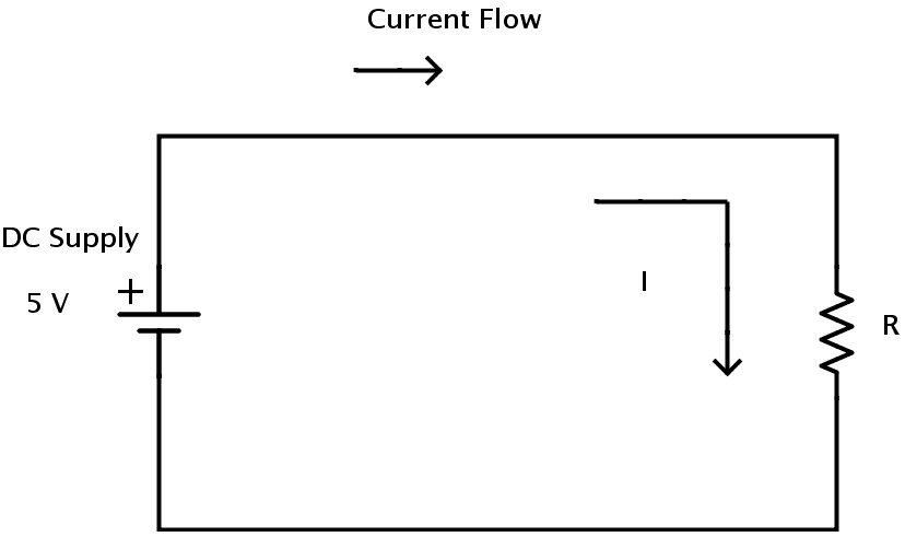
In DC resistive circuits, the resistance which is the ratio of voltage to current is linear.
A resistor with an AC power supply is given below
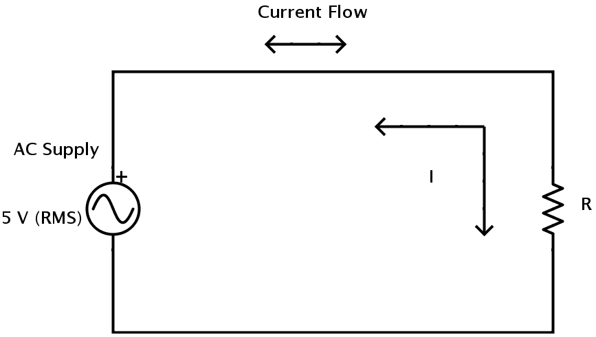
In AC circuits, the voltage to current ratio is mainly dependent on supply frequency f and phase angle orphase difference φ. Hence the term Impedance is used in AC circuits to denote the resistance as it possess both magnitude and phase in contrast to the resistance in DC circuits where is possessed only magnitude. The symbol of impedance is Z.
V-I Phase Relationship in a Pure Resistive AC circuit
The resistance value of the resistor in both AC and DC circuits is same irrespective of the frequency of the AC supply voltage. The change in direction of current in AC supply does not affect resistors behavior. So the current in the resistor will rise and fall according to the voltage as it rises and falls.
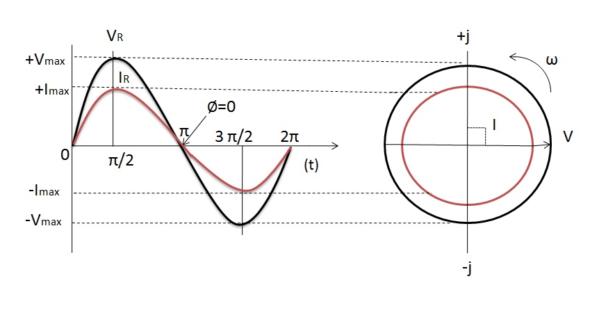
The voltage and current in AC resistive circuit reach maximum, then fall to zero and reach minimum at the same time. They are said to be “in phase” as they rise and fall at exactly the same time.
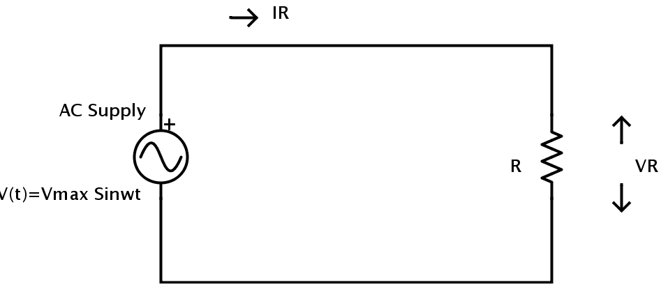
Consider the following AC circuit.
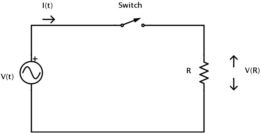
Here the current is I (t) = IMax sin ωt.
The voltage V (t) = VMax sin ωt. => V (t) = IMax R sin ωt.
As the circuit is purely resistive, the effects of inductance and capacitance are negligible and the phase difference is 0.
Hence the relationship between the voltage and current in a resistor which is a part of resistive AC circuit is
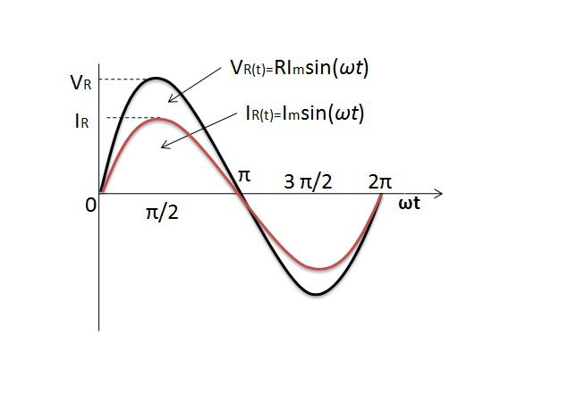
The instantaneous values of currents and voltages are “in phase” along the x- axis of the curve. They rise and fall at the same time and reach their maximum and minimum values exactly at the same time. This implies that their phase angle is θ = 00. The vector diagram representing this phase angle along with a comparison of maximum and minimum values of voltage and current is shown below.
AC Power, Voltage and Current Calculations
The instantaneous values of current and voltage in an AC resistive circuit can be utilized to give the resistance in its Ohmic form by using Ohm’s law.
Consider the following resistive circuit with an AC supply.
Let the supply voltage be V (t) = VMax sin ωt connected to a resistor R.
Let the instantaneous voltage across the resistor be VR.
Let IR be the instantaneous current which is flowing through the resistor.
As the above circuit is pure resistive in nature, the principles of Ohm’s can be applied.
From Ohm’s law, the voltage across the resistor at an instant t is
VR = VMax sin ωt.
Similarly, the current flowing through the resistor at an instant t can be determined using Ohm’s law as
IR = VR / R
But VR = VMax sin ωt.
Hence IR = (VMax * sin ωt) / R
But the value VMax / R is nothing but the maximum current in the circuit denoted by IMax..
Therefore IR = IMax sin ωt.
In a pure resistive series AC circuit the total circuit voltage is equal to the sum of voltages of individual resistors because all the individual voltages are in-phase in pure resistive circuit.In the similar way,the total current in a pure resistive parallel AC circuit is the sum of the individual branch currentsof all the parallel resistive branches.
To calculate power in an AC circuit, the power factor plays an important role. Power factor is defined as the cosine of the phase angle between current and voltage. The phase angle is denoted by the symbol φ.
If P is the real power in a circuit measured in Watts and S is the apparent power of the circuit measured in Volt Amps, the relation between real power and apparent power is given by
P = S Cos φ.
In case of pure resistive AC circuits, the phase angle between current and voltage is 00. Therefore φ = 00. Hence the power factor Cos φ is Cos 00 = 1.
Therefore the real power is equal to the apparent power which is the product of voltage and current.
In pure resistive AC circuits, the power at any instant in the circuit can be found out by calculating the product of voltage and current at that instant.
The power consumed by above mentioned circuit can be calculated using
P = VRMS * IRMS * Cos φ.
As φ = 00 in this case, the power is
P = VRMS * IRMS
Power in a Pure Resistance
In case of pure resistive AC circuits, the power consumed by the circuit is simply the product of voltage and the current as there is no phase angle between current and voltage.
The power waveform for a pure resistive AC circuit is shown below.
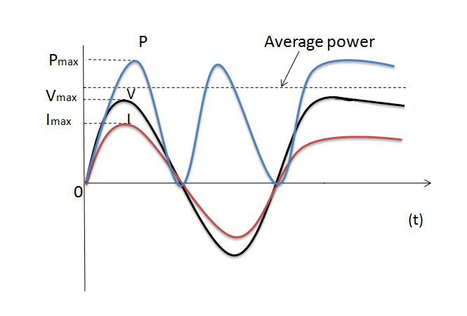
The power waveform consists of a series of positive pulses. This is because when both the voltage and current are positive in the first half cycle, their product which is the power is also positive. And when both the voltage and current are negative in the second half cycle, their productive power isagainpositive (-V x -I = +P). Hence the value of power is always greater than or equal to zero.
From the above waveform, it is clear that the power rises as both the voltage and current rises and reaches its maximum when both voltage and current reach their maximum. Then it falls to zero as voltage and current fall to zero. When the polarity of voltage and current changes the value of power once again rises and reaches a maximum as voltage and current reach their negative peak. When the voltage and the current fall to zero the value of power falls to zero.
In case of pure resistive circuit with an AC RMS power supply, the power dissipated is same as that in case of a resistor connected to DC power supply.
P = VRMS * IRMS = I2RMS * R = V2RMS / R.
VRMS and IRMS are rms values of voltage and current respectively.
P is power in Watts.
R is resistance in Ohms (Ω)
To compare the heating effects caused by AC and DC, the DC current should be compared to the RMS value of AC current but not to the maximum or peak current IMAX¬.
Resistors in AC Circuits Examples
Example 1
Consider the following circuit.
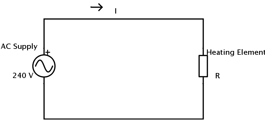
A heating element of resistive in nature is connected to an AC supply of 240 V. The power consumed by the heating element is 1.2 K Watts. The value of its resistance can be calculated as
Current flowing through the heating element is
I = P / V
P = 1.2 K Watts = 1200 Watts.
V = 240 V.
Therefore I = 1200 / 240 = 5 Amps.
The value of the resistance of the heating element can be calculated using Ohm’s law as
R = V / I
R = 240 / 5 = 48Ω.
Example 2
Consider the following circuit.
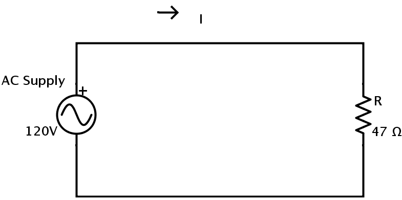
A resistor of resistance 47 Ω is connected to a supply of 120 V.
The values of current flowing through the resistor and the power consumed by the resistor can be calculated as
Current flowing through the resistor can be calculated using Ohm’s law
I = V / R
I = 120 / 47 = 2.55 Amps.
The power consumed by the resistor is
P = I2 * R = V2 / R
P = 1202 / 47 = 306 Watts.

One Response
Very nice content of electronic