Besides the obvious Amplification applications, an Op-amp can also be used for a ton of other applications and circuits. In this tutorial, we will learn about a few frequently used Non-Linear Op-Amp circuits. In Non-Linear Op-Amp circuits, the input / output characteristics are non-linear i.e. not in a straight line.
Introduction
Operational amplifiers, along with linear circuits, are also vastly used to configure non-linear circuits, i.e. circuits whose output exhibits non-linear change with respect to the change in the input. These circuits are commonly known as switching circuits, whose output switches between positive and negative saturation voltage levels. Most popularly used circuit configurations are zero crossing detectors, the Schmitt trigger, astable and monostable multivibrators.
Zero Crossing Detector
A zero crossing detector is the simplest circuit configurations of op-amp switching circuits. In this configuration, the input signal is applied to one of the input terminals while the other input is connected to ground. This circuit needs no feedback connection.
Non-Inverting Zero Crossing Detector
If the input signal source is connected to the non-inverting input terminal of the op-amp and the inverting input terminal is grounded, the circuit is called a Non-inverting zero crossing detector. The circuit diagram is shown in the figure below.
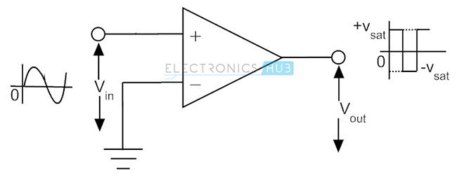
When the input signal is above ground level, the output of the circuit is saturated at its positive extreme. When the input goes below ground level, the output voltage of the circuit immediately switches to its negative saturation level. Every time when the input signal crosses the zero voltage level, the output switches between one saturation level and the other. Since the output of the above circuit goes into positive saturation when the applied input voltage is positive, the circuit is categorized as a non-inverting zero crossing detector. The input and output waveforms of a typical non-inverting zero crossing detector is shown in the above figure. Regardless of the shape of the input wave, the output is always a rectangular wave.
Inverting Zero Crossing Detector
If the input signal is applied to the inverting input terminal of the op-amp, and the non-inverting input terminal is connected to ground, the circuit is called an inverting zero crossing detector. The circuit is shown in the figure below.
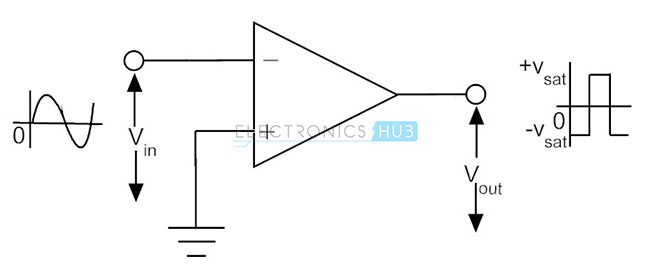
When the input is above ground level, the output is saturated at the negative extreme voltage. When the input voltage goes below ground level, the output immediately switches to positive saturation voltage. Since the output is saturated at negative voltage when the input is positive, this circuit is called as an inverting zero crossing detector. The input and output waveforms of an inverting zero crossing detector is shown in the figure above.
Schmitt Trigger Circuit
A Zero Crossing detector circuit with a feedback connection, usually positive, constitutes the Schmitt trigger. The Schmitt trigger circuit has definite predefined upper and lower input voltage levels that trigger the output to switch from one saturation level to the other.
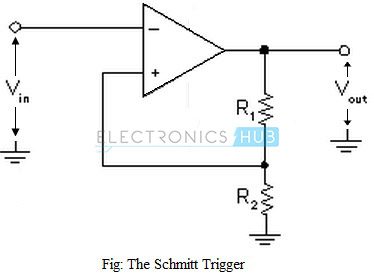
The circuit of a typical Schmitt trigger is as shown in the figure above. The input voltage, Vin, is applied to the inverting input terminal and a part of the output voltage is connected as feedback to the non-inverting input terminal, through a potential divider network. The input voltage Vin triggers the output voltage Vout to change from one saturation level to the other, every time when the input voltage exceeds a certain predefined voltage levels. These voltage levels are called as upper threshold voltage (VUT) and lower threshold voltage (VLT).
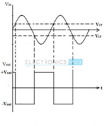
The input and output waveforms of the Schmitt trigger circuit are shown in the figure above. It can be seen that, as long as the input voltage Vin is less than upper threshold voltage VUT, the output voltage is saturated at its positive extreme +Vsat. When the input voltage goes beyond VUT, the output immediately switches to its negative saturation level -Vsat.
The upper and lower trigger points (threshold voltages) can be mathematically obtained by using the relation,
VUT = [R2.(+Vsat)]/(R1+R2) and VLT = R2.(-Vsat)/(R1+R2)
If R2/(R1+R2) = β, then VUT = β (+Vsat) and VLT = β (-Vsat)
Above equations indicate that by appropriately choosing the values of resistor R1 & R2, the upper and lower threshold levels can be adjusted and controlled accurately.
Astable Multivibrator Using Op-Amp
An op-amp astable multivibrator circuit is constructed by adding external components to zero crossing detector or Schmitt trigger circuit. An astable multivibrator is a non-linear circuit configuration using op-amp (the output changes non-linearly with respect to the input), which generates square waves without any external triggering. This circuit has no stable output state, only two quasi-states. The output oscillates continuously between these two quasi-stable states. An astable multivibrator is basically an oscillator, since it requires no external pulse to trigger it. For this reason, the circuit is often referred to as a free running oscillator. However, the circuit uses DC power supply for the op-amp. An astable multivibrator can be configured to produce square waves of required frequency, amplitude and duty cycle.
The circuit diagram of an astable multivibrator using operational amplifier is as shown in the figure below. The circuit is a Schmitt trigger configuration, which has a feedback connection and includes an input capacitor at the inverting input terminal.
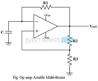
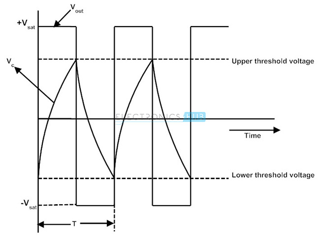
When the astable multivibrator circuit output is at its positive saturation level, current flows through the feedback resistor R1 into the capacitor C. This charges the capacitor, with the top plate positive. The capacitor gets charged until its voltage reaches the upper trigger voltage of the Schmitt trigger. At this point, the output of the circuit switches to its negative saturation level immediately. No current flows into the capacitor now and thus the capacitor starts discharging. The discharging of the capacitor continues till the capacitor voltage reaches the lower trigger voltage of the Schmitt trigger. The output switches to its positive saturation level and the cycle repeats.
It can be noted that the circuit is a square wave generator whose output swings between the op-amp positive and negative saturation voltage levels. The frequency of the output square wave depends on the capacitance C and the feedback resistor value, R1.
The output and the capacitor voltage waveforms of an astable multivibrator are shown in the figure below.
The same circuit configuration can be used to generate square waves of adjustable frequency over a range, by including a potentiometer in series between R2 and R3. By adjusting the resistance value of the potentiometer, the frequency of the output square wave can be varied.
Op-amp Monostable Multivibrator
A monostable multivibrator, like the name suggests, is a circuit that has one stable output state. Its normal output voltage may be high or low, and it stays in that state until triggered. When a triggering pulse is applied, the output switches to the opposite state for a time that is dependent on the RC components of the circuit.
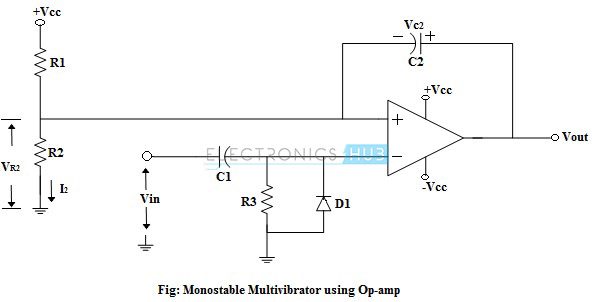
The circuit of a typical monostable multivibrator using an op-amp is as shown in the figure above. The inverting input terminal of the op-amp is grounded through resistor R3 and the non-inverting input terminal is biased positively by resistors R1 and R2. This causes the output to be at its positive saturation level normally, and the capacitor C2 gets charged with the polarity as shown.
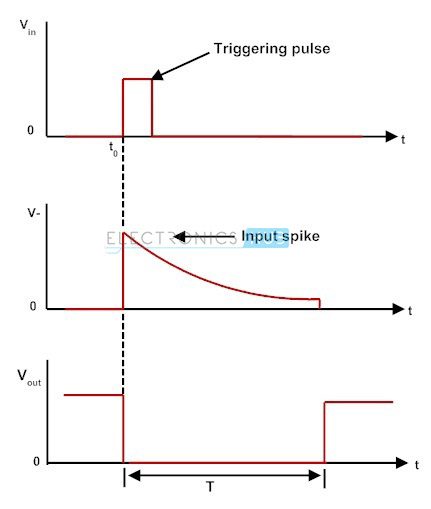
When an input pulse Vin is applied to capacitor C1, the input gets differentiated by C1 and resistor R3, to produce positive and negative spikes at the op-amp inverting input terminal. The negative spike gets clipped at -0.7V by the diode D1, so that the negative spike has no effect on the circuit. The positive spike raises the inverting input terminal voltage above the bias voltage of the non-inverting input terminal. Consequently, the op-amp output switches to its negative saturation level. The time duration of the spike is very short and the inverting input voltage quickly returns to zero. However, when the output goes to negative saturation, the capacitor C2 drives the non-inverting input voltage. This holds the non-inverting input terminal below ground level after the spike has disappeared, thus keeping the output at the negative saturation level.
When the output is at its negative saturation level, the capacitor C2 starts discharging via resistors R1 and R2, gradually raising the non-inverting input voltage to ground level. When the non-inverting input voltage raises slightly above ground level, the output of the op-amp switches to its positive saturation level immediately, and the circuit is returned to its original state. The pulse width of the output wave depends on the capacitance C2 and the bias voltage VR2, and also on the resistances R1 and R2.
The input and the output waveforms of a monostable multivibrator are shown in the above figure.
