An encoder is a device which converts familiar numbers or characters or symbols into a coded format. It accepts the alphabetic characters and decimal numbers as inputs and produces the outputs as a coded representation of the inputs.
It encodes the given information into a more compact form. In other words, it is a combinational circuit that performs the opposite function of a decoder.
These are mainly used to reduce the number of bits needed to represent given information. In digital systems, encoders are used for transmitting the information. Thus the transmission link uses fewer lines to transmit the encoded information.
In addition, these encoders are used for encoding the data which is to be stored for later use as it facilitates fewer bits storing over the available space. Let us discuss various types of binary encoders.
Binary Encoder
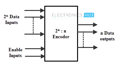
A binary encoder has 2n input lines and n output lines, hence it encodes the information from 2n inputs into an n-bit code. From all the input lines, only one of an input line is activated at a time, and depending on the input line, it produces the n bit output code.
The figure below shows the block diagram of binary encoder which consists of 2n input lines and n output lines. It translates decimal number to binary number.
The output lines of an encoder correspond to either true binary equivalent or in BCD coded form of the binary for the input value. Some of these binary encoders include decimal to binary encoders, decimal to octal, octal to binary encoders, decimal to BCD encoders, etc.
Depending on the number of input lines, digital or binary encoders produce the output codes in the form of 2 or 3 or 4 bit codes.
4 – to – 2 Bit Binary Encoder
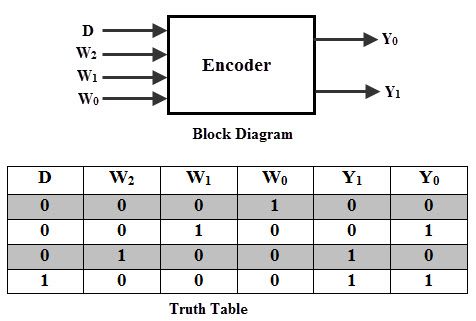
The block diagram and truth table of a 4 input encoder is shown in below figure. The truth table consists of four rows , since , it is assumed that only one input is the value of 1 then the corresponding binary code associated with that enabled input is displayed at the outputs.
It is to be observed from the table is the output Yo is 1 when either input w1 or w3 is 1, also the output Y1 is set to 1 when either input w2 or w3 is 1.
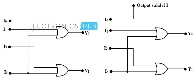
The output from 4-to-2 encoder is generated by the logic circuit implemented by a set of OR gates as shown in below. In the figure a, the output of the encoder is same if the input activated is the Io input (Io = 1) or if no input is activated i.e., all the inputs are zero.
This causes ambiguity in the encoding output. To avoid this ambiguity, a valid encode output can be added as an additional output, so this output assumes a value 1 when Io is equal to 1.

Decimal to BCD Encoder
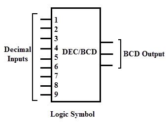
This type of encoder usually consists of ten input lines and 4 output lines. Each input line corresponds to the each decimal digit and 4 outputs correspond to the BCD code.
This encoder accepts the decoded decimal data as an input and encodes it to the BCD output which is available on the output lines.
The figure below shows the basic logic symbol of decimal to BCD encoder along with its truth table. The truth table represents the BCD code for each decimal digit.
From this we can formulate the relationship between the BCD bit and decimal digit. It is important to note that there is no explicit input line for decimal zero. When this condition occurs, i.e., decimal inputs 1 to 9 all are zero, then the BCD output is 0000.
From the above table, we get the expressions as
Y3 = D8 + D9
Y2 = D4 + D5 + D6 + D7
Y1 = D2 + D3 + D6 + D7
Y0 = D1 + D3 + D5 + D7 + D9
From the above expressions, the decimal to BCD encoder logic circuit can be implemented by using set of OR gates as shown in below figure.
Octal to Binary Encoder
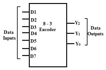
An octal to binary encoder consists of eight input lines and three output lines. Each input line corresponds to each octal digit and three outputs generate corresponding binary code.
In encoders, it is to be assumed that only one input is active or has a value 1 at any given time otherwise the circuit has no meaning. The figure below shows the logic symbol of octal to binary encoder along with its truth table.
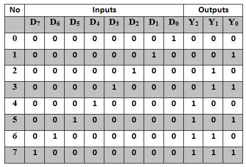
From the above table, the output Y2 becomes 1 if any of the digits D4 or D5 or D6 or D7 is one. Thus, we can write its expression as
Y2 = D4 + D5 + D6 + D7
Similarly, Y1 = D2 + D3 + D6 + D7 and
Y0 = D1 + D3 + D5 + D7
Also it is to be observed that D0 does not exist in any of the expressions so it is considered as don’t care. From the above expressions, we can implement the octal to binary encoder using set of OR gates as shown in figure below.
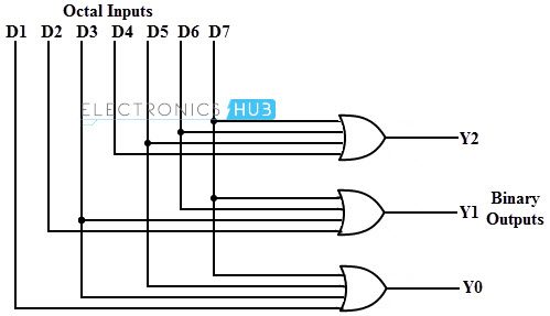
There is ambiguity in the octal to binary encoder that when all the inputs are zero, an output with all 0’s is generated. Also, when Do is 1, the output generated is zero. This is a major problem in this type of encoder. This can be resolved by specifying the condition that none of the inputs are active with an additional output.
Digital Encoder Applications
Encoders are very common electronic circuits used in all digital systems. In case of pocket calculators, these are used to translate the decimal values to the binary in order to perform the binary functions such as addition, subtraction, multiplication, etc.
These are also used to generate the digital signals in response to the movement which are classified into shaft encoders and linear encoders. Let us discuss keyboard applications of encoders in brief.
Keyboard Encoder
This type of encoder function is to generate the binary code corresponds to the alphanumeric character key depressed on a keyboard. The below figure shows a keyboard encoder used to encode the 10 decimal digits in BCD code by using a diode matrix. In this circuit, BCD data are stored in the S-R flip-flops.
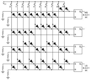
When a key corresponding to one of the decimal digits is pressed, the selected diodes are forward biased by a positive voltage, and these are connected to the set and reset terminals of S-R flip-flops. The diode arrangement is made in such a way that each flip-flop set or resets so as to produce the 4 bit BCD code.
Suppose if key corresponds to decimal digit 7 is pressed, the diodes which are connected to the S inputs of Q4, Q2 and Q1 are forward biased, also the diode which is connected to the R input of Q8. Therefore, the output BCD code is 0111.
From the logic diagram of the encoder, it is to be observed that the diode configuration at each S and R input is essentially a diode OR gate. This type of diode matrix encoders is used in printed circuit boards on many electronic devices having keyboards as user data interface.
