Introduction
In this project, I will show how to operate any electrical without making physical contact with switch by implementing a Wireless Switch Circuit using CD4027 IC.
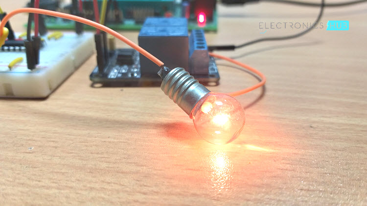
Generally, electrical and electronic appliances that we use in our home are controlled with the help of switches i.e. we toggle the switches to turn the appliance ON or OFF. But in this project, I will show an interesting way to control any device like a Light Bulb for example.
The method implemented here involves a Wireless Switch Circuit where when you slide our hand in front of the circuit, the device (like Lamp) will be turned ON and if you slide you hand once again, the device will be turned OFF.
Using this simple Wireless Switch Circuit, you can avoid the dangers of having physical contact with the switches.
Circuit Principle
The main principle of this Wireless Switch Circuit is in the functioning of LDR, LM741 Op-Amp and a CD4027 JK Flip-Flop IC. In this circuit, all you need is to pass your hand above a simple Light Sensor, the infamous LDR.
The LDR is configured in such a way that, light from an LED will continuously fall on the LDR and when you place your hand over (or pass your hand between the LED and LDR), the device connected to the circuit will turn ON.
This change is detected by an Op-Amp (LM741 is used here) and triggers a flip-flop (CD4027 is used). The device will stay turned ON untill you pass your hand over the LDR again.
Related Post: JK Flip Flop using CD4027
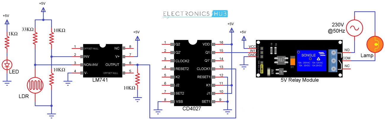
Circuit Diagram of Wireless Switch Circuit using CD4027
The following image shows the circuit diagram of the project.
Components Required
- CD4027 – 1
- LM741 – 1
- Resistors
- 10KΩ – 3
- 33KΩ – 1
- 1KΩ – 1
- LDR
- LED
- 5V Relay Module
- Lamp
Circuit Design
The design of the circuit is very simple. First, connect a voltage divider (using either two resistors or a potentiometer) to the Inverting terminal (Pin 2) of the Op-Amp LM741. Now, Connect the combination of LDR and a resistor (which again form a voltage divider) to the Non-Inverting terminal (Pin 3) of the Op-Amp.
Place an independent LED (with current limiting resistor) in from of the LDR so that the light from LED will always fall on the LDR.
Connect the output (Pin 6) of the Op-Amp to the clock (Pin 13) of the Flip-Flop IC CD4027. The output of the Flip-Flop (Pin 15) is connected to the Relay Input of the 5V Relay Module.
Finally, connect the J (Pin 10) and K (Pin 11) Pins of CD4027 to +5V and Set (Pin 9) and Reset (Pin 12) to GND. Rest of the connections with respect to power supply are self explanatory.
NOTE: In place of two fixed resistors that are connected to the Inverting Input of the Op-Amp, you can connect a Potentiometer and vary the sensitivity of the circuit.
WARNING: If you are planning to use a real light bulb (that run on AC Mains Supply) with the relay module, you must be extremely careful when making the connections.
Wireless Switch Circuit Working
It is very simple to understand the working of the circuit. The circuit mainly depends on two ICs. First one is LM741, which is an Operational Amplifier. The LM741 Op-Amp is employed as a comparator for sensing LDR voltage and a reference voltage.
Another one is the JK Flip-Flop IC CD4027. It consists of two JK Flip-Flops with individual Set and Reset pins. CD4027 is used to alter the state when the signal is given to the any one of the input terminals and can get more than single output.
Under normal conditions, the output of the Op-Amp is always LOW since the LDR will continuously receive the light from the LED.
Now, as soon as someone passes their hand over the LDR, Pin 3 of the Op-Amp will be at a higher voltage when compared with the Pin 2 and as a result the Pin 6 will become High for a moment.
This HIGH state is supplied as clock pulse to Pin 13 of CD4027 (flip flop IC). As both J and K inputs of the flip-flop are tied HIGH, a clock pulse will toggle the Output i.e. will make the Output HIGH.
As this Output pin of CD4027 is connected to the input of the relay, the lamp connected to the relay will be turned ON.
If you pass your hand over the LDR once again, the process repeats and this time, the output of the CD4027 IC will become LOW (Toggle from HIGH to LOW). This will result in a LOW input on the relay and the lamp will be turned OFF.

14 Responses
nice……..
Good
nicely done. The LDR’s resistance?
because of the voltage divider between LDR and R2, LDR should be about the same resistance?
the sensitivity control, pot VR1 would have to always be wiper-halfway then…
nice circuit!
WHAT kind of relay are we going to use?
where to connect this circuit.?
to the device or replace it with the present switch.?
nice idea
What relay should I use? And where do I connect the load. Help me please!
Use a 5v relay and connect the load to No and NC pins of the relay
can anyone tell me what is the relay used in this circuit?
Use a 5v relay
where to use this circut
What is the use of capacitor c1 here…?
Do we have to supply Ac source to relay.
And how to do connection of relay.I connected all the thing but at last where there is relay I am getting confused of giving connection to it. Also do I need two battery or one battery and Ac source or only one battery to give supply to circuit. Please reply me fast I have to make this project
I have this little circuit from a remote controlled moon lamp. Can somebody help me pls??