A power outlet allows electrical equipment and appliances to get connected to AC power. Arduino can be used to control this power outlet in order to turn the electrical equipment or appliance in to a smart device. Normally, we plug in different appliances or electrical devices in to the wall socket and turn them ON or OFF with the help of associated switches on the wall.
In this project, we have used Arduino to control a Power Outlet so that it can be controlled with the help of a sensor or remote switch. We have designed a Power Outlet box with one plug and a switch that is connected to a relay module, which is controlled by the Arduino. For triggering the relay, we have used an LDR light sensor.
Alternatively, the Power Outlet can be made to work with Bluetooth, over the internet with Wi-Fi Module (ESP8266) or any other type of sensor.
Arduino Controlled Power Outlet

WARNING: We are going to connect 230V AC to the Power Outlet Box and the 5V Relay Module. It is very dangerous and you should be very careful while making the connections. Make sure that nothing is plugged in while connecting and switch on the supply only after double checking the connections.
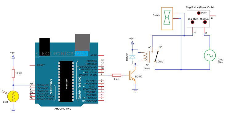
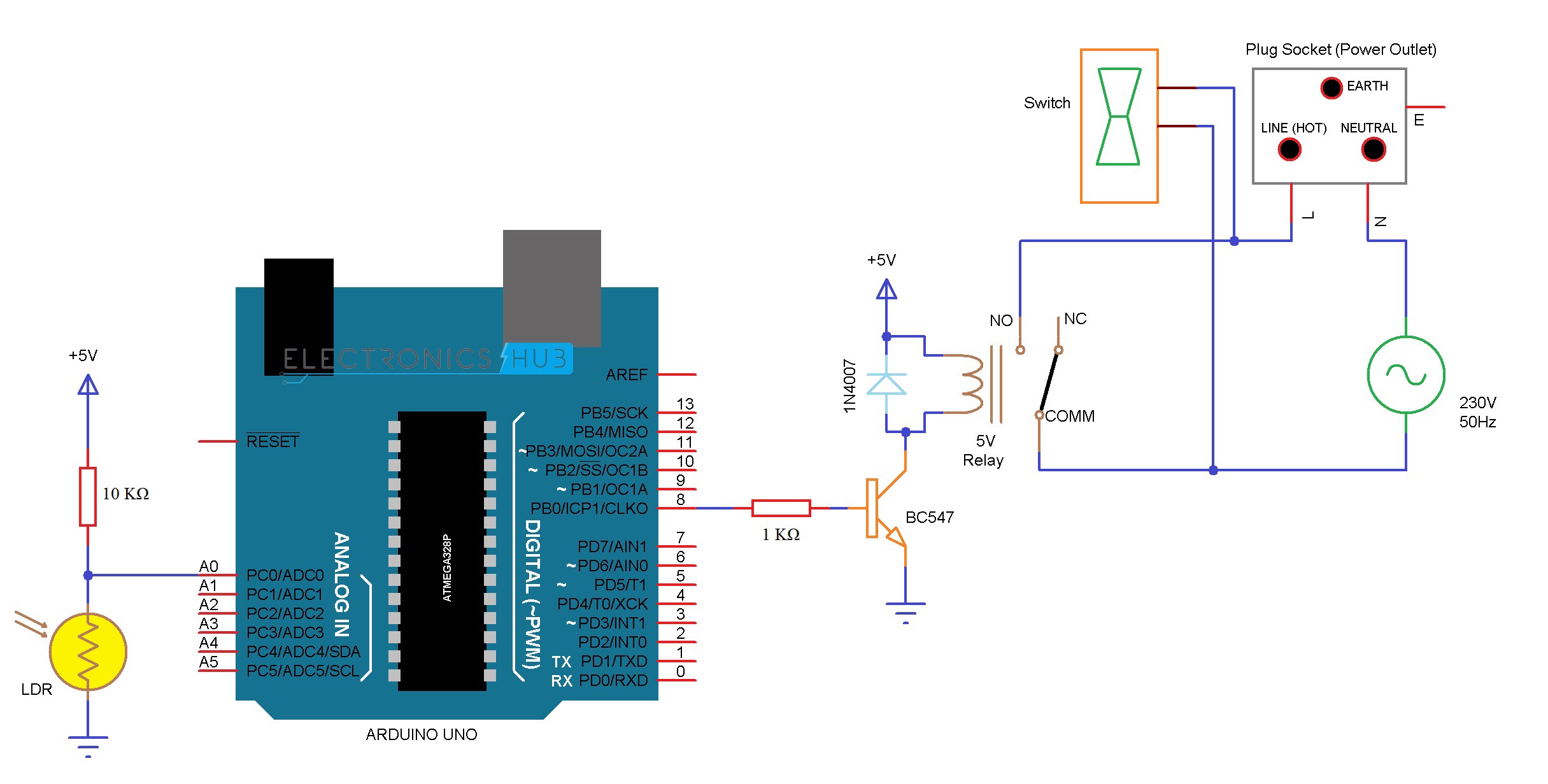
Circuit Diagram
Component Required
- Arduino UNO [Buy Here]
- 5V Relay Module
- ON – OFF Switch
- A Power Outlet (Plug or Socket)
- LDR (Light Dependent Resistor)
- 10 KΩ Resistor (1/4 Watt)
- Power Supply
- Connecting Wires
If Relay Module is not used, then we need the following components
- 5V Relay
- BC547 (NPN Transistor)
- 1N4007 PN Junction Diode
- 1 KΩ Resistor (1/4 Watt)
Component Description
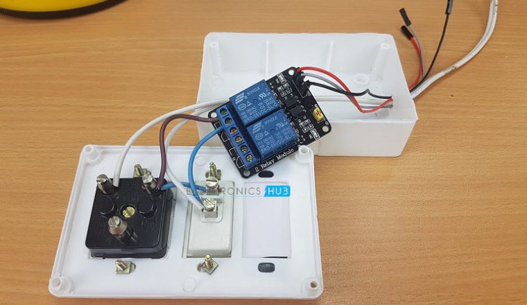
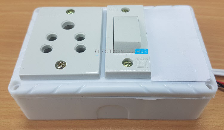
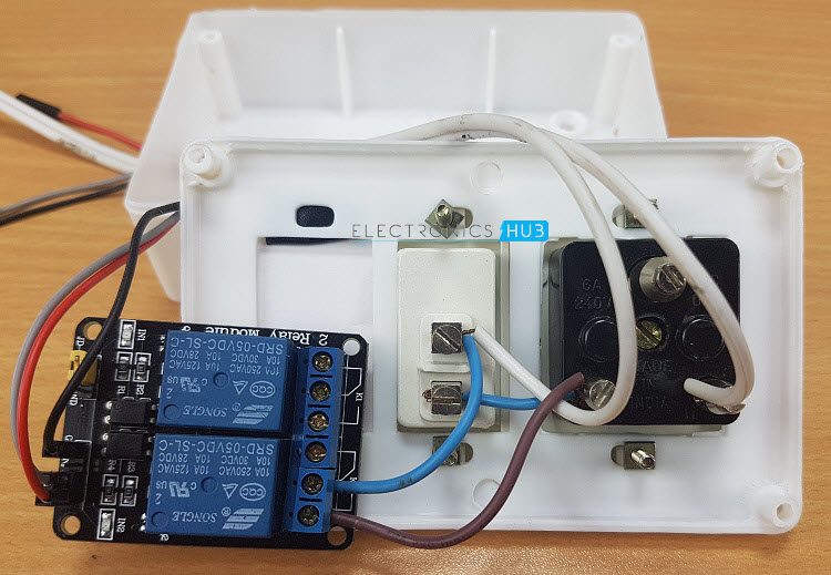
Power Outlet and Switch
We have used a single power outlet box with control switch. This particular socket is rated for 250V and 6A. So, any electrical device with power consumption up to 1200W (just to be on the safe side) can be easily used with this outlet.
5V Relay Module
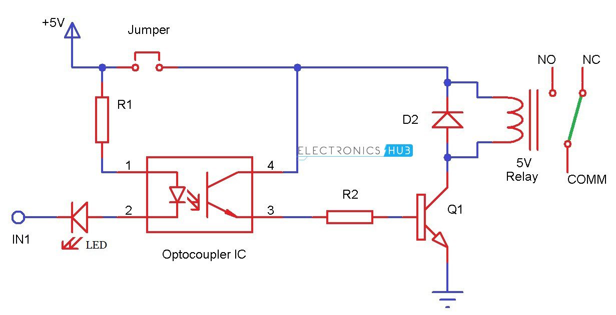
The 5V Relay Module is an important component of this project. It runs on 5V and hence, can be powered using the Arduino itself. This particular module consists of a 5V Relay, a transistor, a Zener Diode, an Optocoupler IC, couple of LEDs, corresponding current limiting resistors, screw terminals and few male headers for connecting power and other inputs.
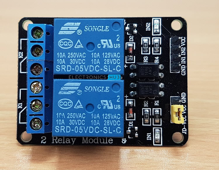
The circuit diagram of the 5V Relay Module is shown in the following image. From the circuit, it is clear that the 5V Relay Module is an active LOW module i.e. a logic ‘0’ from Arduino will turn ON the relay and vice – versa.
LDR (Light Dependent Resistor)
An LDR (Light Dependent Resistor) is used to sense the light falling on it and accordingly vary the output voltage. This voltage is read by the Arduino and will trigger the Relay.
Circuit Design
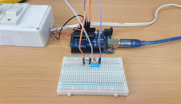
The design of the circuit is clearly expressed in the circuit diagram. We will see a detailed explanation of the circuit here. First, an LDR and a 10 KΩ Resistor are connected to form a voltage divider and the output of the divider i.e. the connections midpoint is connected to analog input pin A0.
Coming to the relay, the 5V and GND pins for the relay module are given from the Arduino UNO. The control pin for the relay is connected to the pin 8 of Arduino.
Finally, the power outlet box. We need to open the box and make connections. First connect neutral wire from the supply to neutral connector on the socket. Connect the other connector on the socket to one end of the switch (bottom terminal) and also to the NO (Normally Open) contact of the Relay.
The second terminal of the switch (top terminal) is connected to the Line (Hot) wire from the supply and also to the COMM (Common) terminal of the Relay.
CAUTION: Be very careful when using AC Mains lines. It is very dangerous and could kill you.
Working of the Project
A Power Outlet box that is controlled using Arduino is designed here. The working of the project is pretty straight forward and is explained here.
The connection between the Arduino and the power outlet is made through a 5V Relay Module. The switch provided on the power outlet box can be normally used to turn ON or OFF the appliance plugged in to the socket.
Since the Relay is also connected to the Socket, we can control the appliance with the relay as well. To make the project a little bit interesting, we have used a simple light sensor in the form of an LDR (Light Dependent Resistor) to trigger the relay.
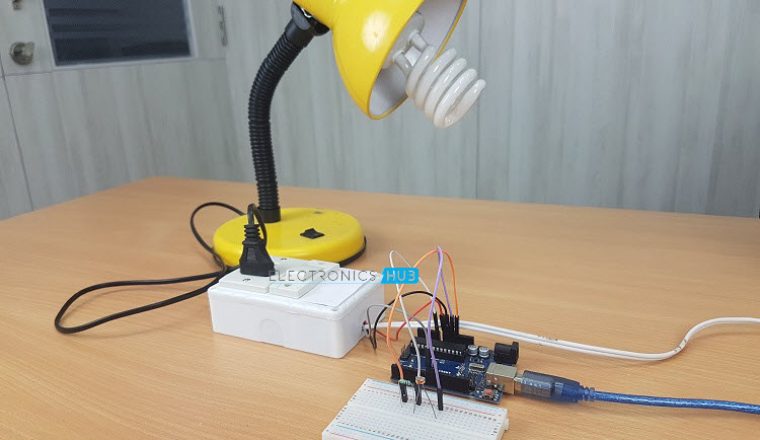
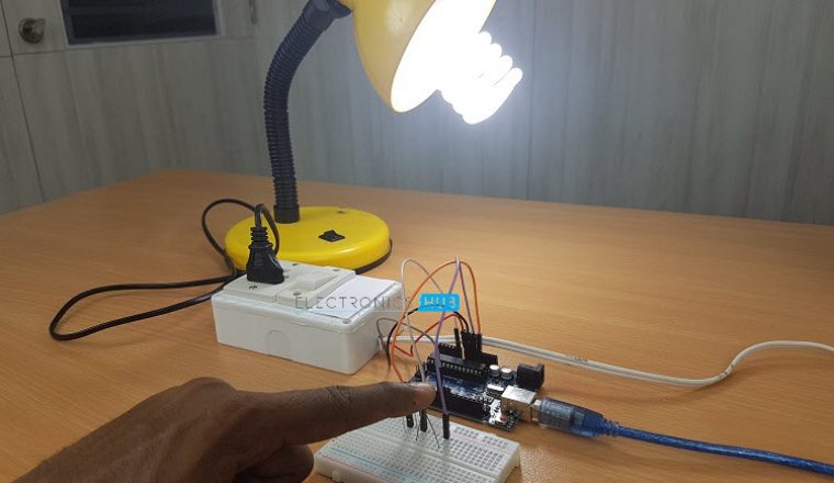
Arduino will continuously monitor the readings from the LDR and when there is no light falling on the LDR (darker conditions), the Relay is activated and hence the appliance or device connected to the power outlet box will also be turned.
When the intensity of the light falling on the LDR increases, the relay will be deactivated and appliance will be turned OFF. For demonstration purpose, we have connected a 27 Watt CFL light to the power outlet.
An Interesting Observation
If you observe from the circuit diagram, the switch on the power outlet box and the relay terminals are connected in parallel forming a circuit similar to the following image.
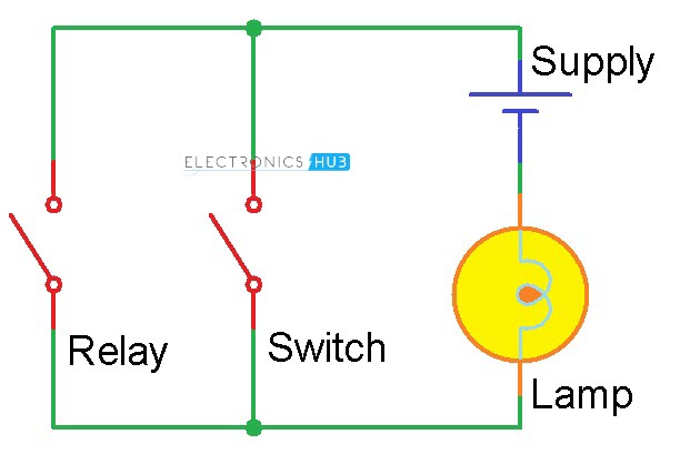 From the above circuit, either of the switches can be used to control the light and if one is active, the other switch is automatically doesn’t have a chance to control the appliance as this is not a Stairway Switch connection.
CODE
Applications
- The Arduino Controlled Power Outlet can turn any electrical device into a smart appliance.
- We have used a light sensor in the form of LDR to control the power outlet, but there are many other ways to control it like mobile phone, internet etc.
- Arduino Controlled Power Outlet can be used in special applications like sensing the water level and automatically turning the motor, turning on a fan when the temperature increases etc.
Construction and Output Video
Recommended read:

5 Responses
hi good day, i like your work and i have a little bit question is it connected to the main source?, i mean the lamp,, is it connected to the 220v or something?,,,
Hello, where is the code for this project ? I cannot find it anywhere
Hello, I attached the project to an external power supply but it’s not working as shown. Is there something I need to add to the code? I added an external 12VDC plug. Can you please help me? Thank you. The outlet just stays on and the switch doesn’t turn it off. As well as when I put my hand over the LDR it doesnt turn it on or off.
I want to ask something is it easy to check the current consumption in this construction?
If this is possible, it happens with the use of code or a sensor?
Swap to Indonesian
Hello Friend
I want to ask for help, regarding Battery Charge Control …
in component circuits that I use Arduino, Mosfet and Voltege Sensors but still confused in the Arduino IDE Program Language