A Switch is an electromechanical device that can make or break an electrical circuit. A simple switch consists of two metal or other conductive materials that are connected to an electrical circuit.
When they touch, the circuit is complete and allows flow of current. When they are separated, the circuit is open. There are many types of switches used in electrical and electronic circuits.
Some of the commonly used switches are Slide Switch, Toggle Switch, Flip Switch, Push Button, Rotary Switch etc.
 All the above mentioned switches are mechanical switches and must be operated manually. A Relay is a type of mechanical switch that can be controlled through electrical signals.
A wireless switch is a type of switch that can be used to control electrical appliances without making any physical contact. The most common type of wireless communication between the switch and the appliance is RF transmission.
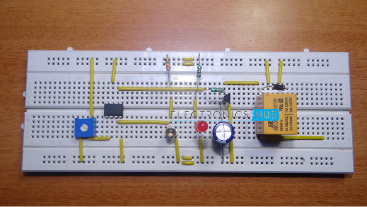
In this project, we designed a simple wireless switch that uses simple hardware to achieve the action of switching. The circuit diagram, circuit description and working are described in the following sections.
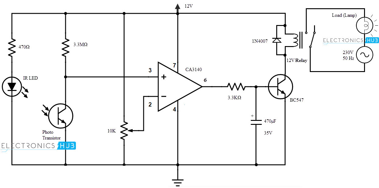
Wireless Light Switch Circuit Diagram
Components Required
- CA3140 Operational Amplifier – 1
- Photo Transistor (L14F1) – 1
- IR LED – 1
- BC547 – 1
- 1N4007 – 1
- 12V Relay – 110 KΩ POT – 1
- 3.3 MΩ – 1
- 3.3 KΩ – 1
- 470Ω – 1
Component Description
CA3140
It is a BiMOS Operational Amplifier that combines the features of Bipolar and MOS technologies. The input stage of CA3140 is MOSFET (PMOS to be specific) and the output stage is Bipolar.
Both the input and output stages are high voltage compatible. The minimum and maximum operating supply voltages are 4V and 36V respectively.
Some of the applications of CA3140 are sample and hold amplifier, function generators, power supplies, comparators, filters, all operational amplifier applications etc.
Photo Transistor (L14F1)
L14F1 is a photo Darlington Transistor. It has a narrow reception angle.
IR LED
An IR LED is a special type of LED that emits infrared rays. It emits rays at a wavelength that is higher than that of the visible light. Hence, the emission is not visible to the human eye. IR Receivers or photo transistors are used to detect the IR rays from IR LED.
Circuit Design of Wireless Switch
The BiMOS Operational Amplifier is designed as a comparator.CA3140 is an 8 pin IC. Pins 7 and 4 are supply pins and are connected to supply and ground respectively.
Pins 2 and 3 are the input pins. Pin 2 is inverting input and is given to the wiper of a 10 KΩ POT. The other terminals of the POT are connected to Vcc and Gnd to complete the voltage divider.
The non-inverting pin (Pin 3) of the operational amplifier is connected to the collector of the photo transistor (L14F1). A 100 KΩ resistor is connected between Vcc and collector of the photo transistor.
The emitter of the photo transistor is connected to ground. An IR LED is connected before the photo transistor with a current limiting resistor (470Ω).
Pin 6 of CA3140 is the output pin. It is connected to the base of a transistor (BC547) via 3.3 KΩ resistor. A 470 µF capacitor is connected from base of BC547 to ground.
The emitter of the transistor is connected to ground. One end of the relay coil is connected to the collector of BC547 while the other end is connected to 5V supply.
A diode (1N4007) is connected across the coil terminals of the relay to block reverse current. The contacts of the relay are connected to a load and AC mains supply.
Working of Wireless Switch
 The aim of this project is to implement a wireless switch which will turn on or off any electrical appliance without physical contact with the switch.
The construction of the project is very simple as the hardware used is very little. The working of the wireless switch is explained here.
The project works on the principle of photo detection or light detection. IR LED continuously emits infrared radiations. These radiations fall on the photo transistor and provide a base current to the photo transistor which will turn on the transistor.
As long as the transistor is on, the input at non-inverting terminal (Pin 3) of the operational amplifier CA3140, which acts as a comparator, is less than that of inverting terminal (Pin 2).
The output of the op amp is low. As a result, the transistor (BC547) that is connected to the output terminal (Pin 6) is off. The relay is not energized and the load stays off.
When there is an interruption to the light falling on the photo transistor, due to placing an object like a hand between the IR LED and photo transistor, there will be no base current to the photo transistor and as a result it is turned off.
As the photo transistor is off, the input to the non – inverting terminal of the op amp will be higher than the inverting terminal. Hence, the output of the op amp is high.
This will turn on the transistor BC547 and the relay is energized. The load that is connected to the relay coils is turned on.
NOTE
- The contacts of the relay are connected to mains supply. Utmost care must be taken while dealing with AC mains.
- Any electrical appliance can be used as the load and the Ampere rating of the relay is important depending on the load.
- Can be used to wirelessly switch on or off devices without any physical contact with the switch.

8 Responses
In light switch project i don’t undrerstand that how your are giving the input ,in the video it is hidden,as in the circuit diagram load is connected to ac source but in video load is connected to relay,kindly guide me
Hi,
Load is connected to AC Source through Relay.
How much input is given this project
12V DC from a wall adapter.
Plz tell me photo transistor connection
are there any equations used?a theoretical part
Not really. It is simply based on the Op Amp (you must be familiar with its working).
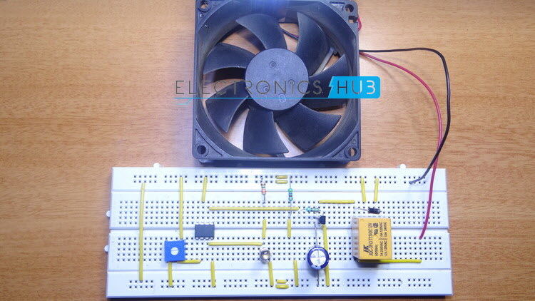
The fan used is DC fan or Ac fan?