An oscilloscope is probably the most commonly used lab equipment by electrical and electronics engineers (apart from a multimeter). But what is an Oscilloscope? What are the different types of Oscilloscopes? How does an Oscilloscope work? Let us try to understand all these in this introductory Oscilloscope guide.
What is an Oscilloscope?
An Oscilloscope is an electronic test and measurement instrument that graphically displays electrical signals in the form of an X-Y plot. Here, the horizontal (X) represents the time and the vertical (Y) axis represents the magnitude of voltage. So, an Oscilloscope essentially displays a graph of how the voltage of electrical signal changes over time. As a result, earlier Oscilloscopes are called Oscillographs.
While a multimeter also measures the voltages of an electrical signal, an Oscilloscope takes this measurement to the next level by visually representing the signal using a waveform. By plotting such waveforms, essential properties of the signal such as amplitude, frequency, period, rise and fall times, etc. can be easily interpreted.
For example, if you are designing a 12V power supply, a multimeter can only display whether the output of your power supply is 12V or not. Oscilloscope, on the other hand, can display the waveform of the output power where you can analyze the noise, ripples, switching frequency, etc., and make any improvements or corrections.
A Brief History of the Oscilloscope
Do you remember CRT TVs? Those bulky and heavy television units have a cathode ray tube that is responsible for displaying the image on the screen. In fact, Ferdinand Braun in 1897 developed the first Oscilloscope while experimenting on Cathode Ray Tubes. In 1899, Jonathan Zenneck developed the first Oscillogram by adding beam-forming plates and applying a linear horizontal magnetic deflection field.
All these experiments mostly resulted in laboratory useful devices but this changed in 1931 when Dr. V. K. Zworykin published a paper on CRT that solved the problems of hot cathode and vacuum. This eventually led General Radio to release the first portable CRT-based oscilloscope.
Fun Fact: As the original oscilloscope was developed using Cathode Ray Tube technology, the earlier oscilloscopes are called Cathode Ray Oscilloscopes or CRO for short. The term ‘CRO’ became a popular industry term and even today, many senior engineers use CRO synonymous with oscilloscope even though most of the modern oscilloscopes are digital with LCD displays.
The developments in semiconductor technology (processors, memories, and data converters), LCD Display technology, and also the increasing cost of CRTs have made engineers venture into Digital Oscilloscopes. Most modern oscilloscopes are called Digital Storage Oscilloscopes (DSO) as they capture and store the trace for re-investigation.
Types of Oscilloscopes
Basically, Oscilloscopes are of two types.
- Analog
- Digital
This classification became important only after the development of Digital Storage Oscilloscopes in the 1990s.
What is an Analog Oscilloscope?
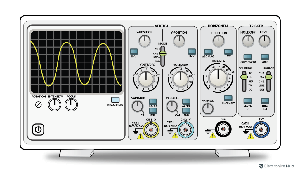
Earlier CROs are analog oscilloscopes. They are very simple as there is no need for any sort of signal processing and the electrical signals are displayed as a waveform as is using high gain amplifiers.
A simple CRO consists of a CRT (cathode ray tube), vertical and horizontal amplifiers, triggering unit, time base (sweep generator), and power supply.
What is a Digital Oscilloscope?
The main difference between analog and digital oscilloscopes is that in Digital Oscilloscopes, the analog signal is captured and converted into a digital signal using an Analog to Digital Converter.
The advantage of using Digital Oscilloscopes is that you can easily store the digital data in digital memory. This is the main feature of Digital Storage Oscilloscopes or DSOs, where a portion of the trace is captured and can be analyzed later.
Before the usage of LCD displays, digital oscilloscopes still used CRTs for displaying the signal. Such oscilloscopes require a digital to analog converter to convert the digital signals back to analog signals and display them on the CRT. But with LCD displays, we can avoid this step completely as the digital signals can be directly displayed on LCD (with some transformation).
Digital Oscilloscopes are further classified into:
- Digital Storage Oscilloscopes (DSO)
- Mixed Signal Oscilloscope (MSO)
- Digital Phosphor Oscilloscope (DPO)
- Mixed Domain Oscilloscope (MDO)
- Digital Sampling Oscilloscope
How does an Oscilloscope Work?
Now that we have seen what is an Oscilloscope and the two basic types of oscilloscopes, let us now try to understand how an oscilloscope works. As there are analog and digital oscilloscopes in general, we will see how each of these works.
Analog Oscilloscope
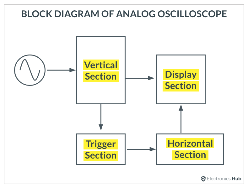
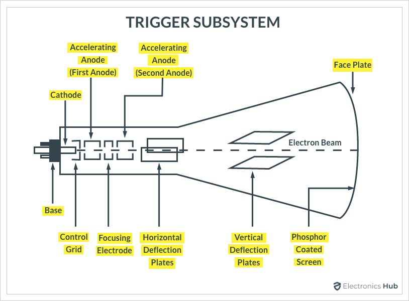
CRT is the main part of all analog oscilloscopes. If we can understand how a CRT works, then we can easily know how to display a waveform on the screen of CRT. The following image shows the basic building blocks need to display a waveform on a CRT.
Vertical Section in the above block diagram is responsible for sending the main image to the vertical deflection plates of the CRT. The vertical section amplifies or attenuates the input signal. Horizontal Section is responsible for the movement of the electron beam from left to right. Trigger Section determines when to draw the waveform on the CRT.
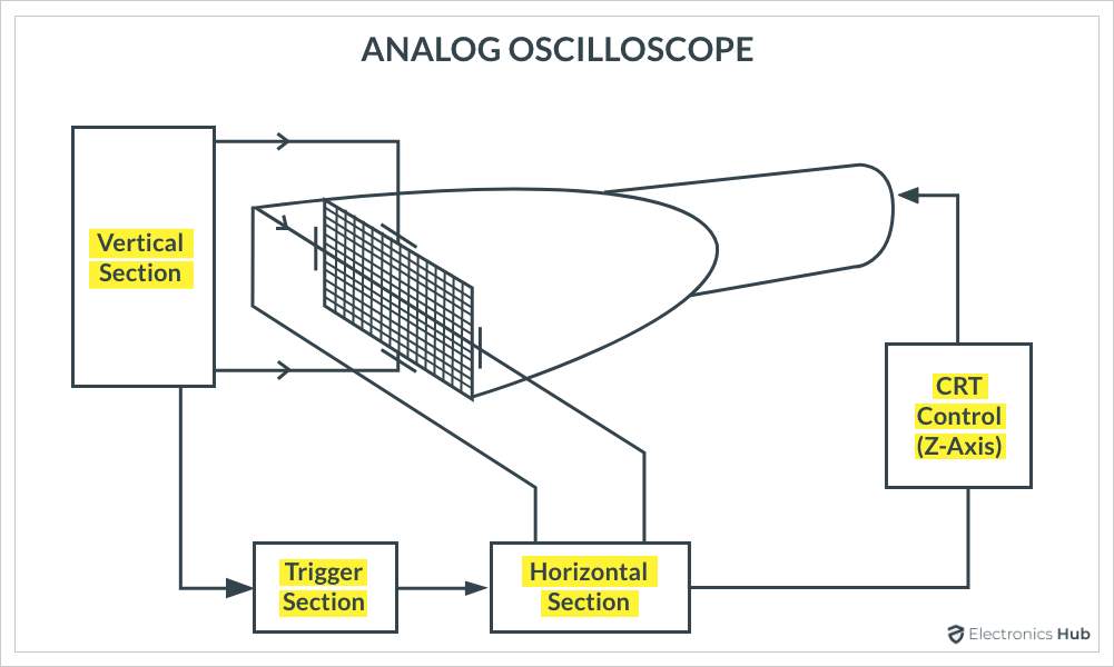
Display System
The following image shows a simplified display system of an analog oscilloscope. The Z-axis circuit in the block diagram is responsible for controlling the brightness of the electron beam.
Vertical System
In its basic form, the vertical system of an analog oscilloscope consists of an attenuator, pre-amplifier, delay line, and main amplifier. The following image shows the block diagram of the vertical system of an oscilloscope.
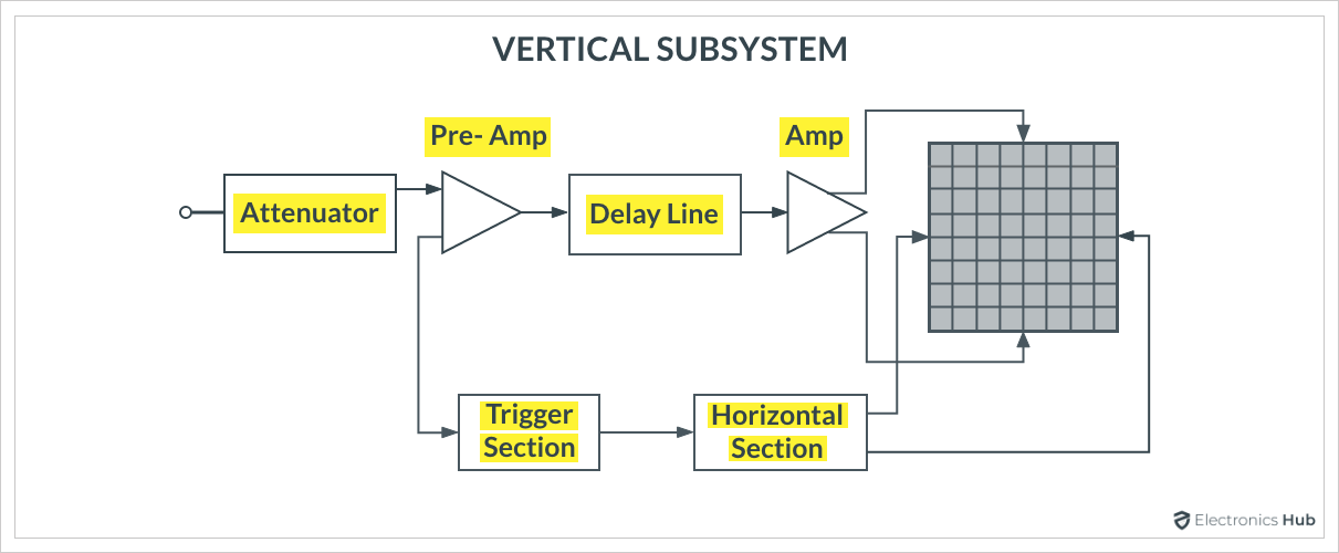
The attenuator part of the vertical system attenuates the input signal and also allows AC or DC coupling. The pre-amp stage is responsible for changing the DC component of the signal and as a result, it allows for changing the position of the trace. The delay line of the vertical section makes it possible to display the beginning of the signal.
Horizontal System
To properly display the signal on the oscilloscope, both the vertical and horizontal systems are equally important. While the vertical system is responsible for the amplitude part of the signal, the horizontal system brings in the 2nd dimension i.e., the time aspect of the signal.
The horizontal system provides the deflection voltage to the horizontal plates to move the electron beam horizontally. To do this, a sweep generator circuit generates a saw-tooth (or a ramp) signal to control the sweep rate of the beam.
The following image shows the block diagram of the horizontal system of an oscilloscope. The saw-tooth or ramp signal rises linearly and enables the measurement of time between two events. The sweep generator is calibrated in time and as a result, it is also known as Time Base.
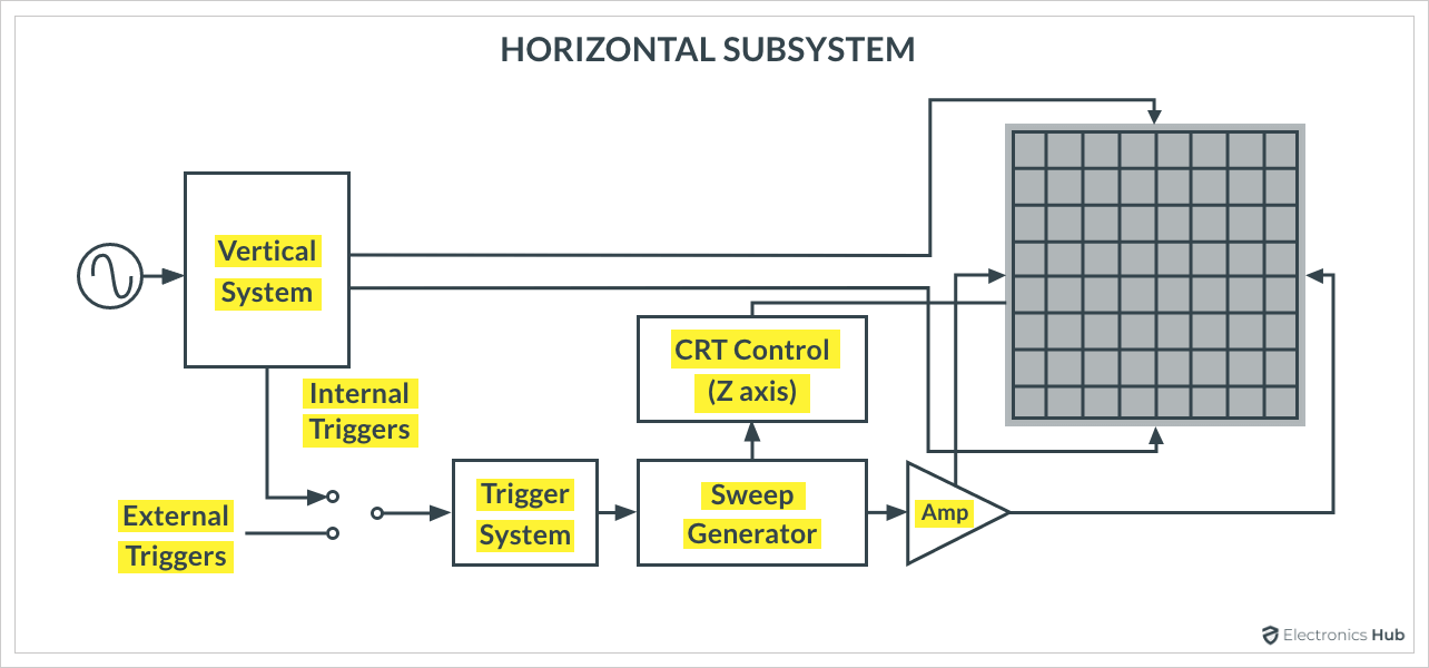
In addition to the time base, the earlier spoken Z-axis control system is also a part of the horizontal system.
Trigger System
The last important part of the oscilloscope is the trigger system. This system determines the time at which the oscilloscope draws the waveform on the screen.
CRT’s screen is coated with phosphorus on the inside so that when an electron strikes it, the screen emits light. The horizontal system is responsible for moving the beam from left to right. When it reaches the far right of the screen, it rapidly returns to the left to start the process once again. This process is called Sweep (or Trace or Scan).
The vertical system is responsible for moving the beam vertically. Trigger System of the oscilloscope makes sure that the trace of the waveform always starts at the same point on the screen.
Digital Oscilloscope
Let us take a digital oscilloscope with CRT as a reference to understand the working. The following image shows a simplified block diagram of a typical digital oscilloscope with a CRT display.
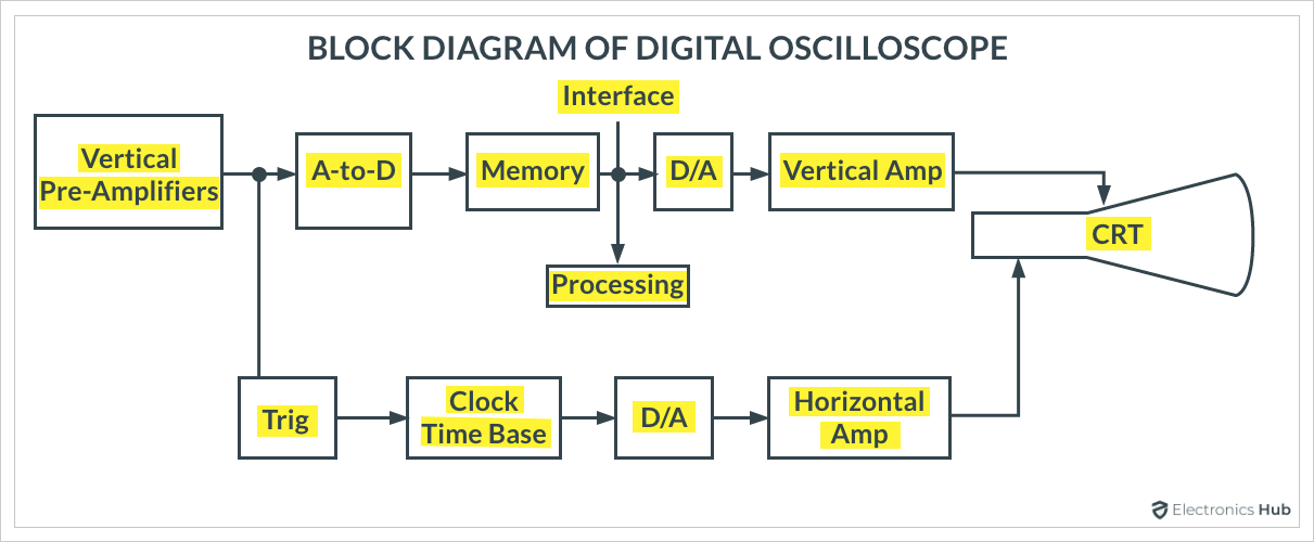
The main difference lies in the vertical system of the oscilloscope. So, let us focus only on that as the remaining working will be similar to that of an analog oscilloscope.
After the attenuation and pre-amp stage, the analog signal is converted into a digital signal using an ADC (analog to digital converter). The digital signal is then given to a processing unit, which performs some signal processing (calculate basic parameters, store it in memory, etc.). In order to display the signal on CRT, the digital signal must be converted back to analog with the help of a digital to analog converter.
Conclusion
We presented an introductory guide on oscilloscopes in this article. We learned what is an oscilloscope, what are the different types of oscilloscopes, the basic components of an oscilloscope, and how analog and digital oscilloscopes work. There is much more to explore in the world of oscilloscopes and in the future, we would like to update this page with more information.

3 Responses
Quite good and essential
A very nice article covering almost everything about analogue and digital oscilloscope…
Very helpful those interested in electronics, i expect to know more like DSO. The new generation must have basic knowledge and history of oscilloscope.