In the previous tutorial we have learned about asynchronous counters. Though they are easily built there is time delay in their operation.
The counters which use clock signal to change their transition are called “Synchronous counters”. This means the synchronous counters depends on their clock input to change state values. In synchronous counters, all flip flops are connected to the same clock signal and all flip flops will trigger at the same time.
Synchronous counters are also known as ‘ Simultaneous counters ’.There is no propagation delay and no ripple effect in synchronous counters.
Different types of Synchronous Counters
There are many types of synchronous counters available in digital electronics. They are listed below.
- Binary counters
- 4 bit synchronous UP counter
- 4 bit synchronous DOWN counter
- 4 bit synchronous UP / DOWN counter
- Loadable counters
- BCD counters
- Ring counters
- Johnson counters etc.
4 bit Synchronous UP Counter
The 4 bit up counter shown in below diagram is designed by using JK flip flop. External clock pulse is connected to all the flip flops in parallel.
For designing the counters JK flip flop is preferred .The significance of using JK flip flop is that it can toggle its state if both the inputs are high, depending on the clock pulse.
The inputs of first flip flop are connected to HIGH (logic 1), which makes the flip flop to toggle, for every clock pulse entered into it. So the synchronous counter will work with single clock signal and changes its state with each pulse.
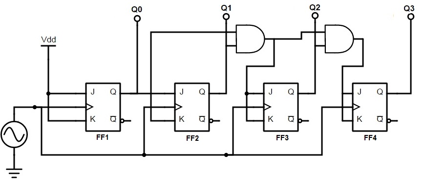 The output of first JK flip flop (Q) is connected to the input of second flip flop. The AND gates (which are connected externally) drives the inputs of other two flip flops . The inputs of these AND gates , are supplied from previous stage lip flop outputs.
[adsense2]
If inputs of FF2 are connected directly to the Q1 output of FF1 , the counter would not function properly. This is because , the Q1 value is high at count of 210 , this means that the FF2 flip flop will toggle for the 3rd clock pulse. This results in wrong counting operation, gives the count as 710 instead of 410.
To prevent this problem AND gates are used at the input side of FF2 and FF3. The output of the AND gate will be high only when the Q0, Q1 outputs are high. So for the next clock pulse, the count will be 00012.
Similarly, the flip flop FF3 will toggle for the fourth clock pulse when Q0, Q1 and Q2 are high. The Q3 output will not toggle till the 8th clock pulse and will again remain high until 16th clock pulse. After the 16th clock pulse, the q outputs of all flip flops will return to 0.
Operation
In the up counter the 4 bit binary sequence starts from 0000 and increments up to 1111.Before understanding the working of the above up counter circuit know about JK Flip flop.
In the above circuit as the two inputs of the flip flop are wired together. So , there are only two possible conditions that can occur, that is, either the two inputs are high or low.
If the two inputs are high then JK flip-flop toggles and if both are low JK flip flop remembers i.e. it stays in the previous state.
Let us see the operation. Here clock pulse indicates edge triggered clock pulse .
1.) In the first clock pulse, the outputs of all the flip flops will be at 0000.
2.)In the second clock pulse, as inputs of J and k are connected to the logic high, output of JK flip flop(FF0) change its state .Thus the output of the first flip-flop(FF0) changes its state for every clock pulse .This can be observed in the above shown sequence .The LSB changes its state alternatively. Thus producing -0001
3.) In the third clock pulse next flip flop (FF1) will receive its J K inputs i.e (logic high) and it changes its state. At this state FF0 will change its state to 0. And thus input on the FF1 is 0.Hence output is -0010
4.) Similarly, in the fourth clock pulse FF1 will not change its state as its inputs are in low state, it remains in its previous state. Though it produces the output to FF2, it will not change its state due to the presence of AND gate. FF0 will again toggle its output to logic high state. Thus Output is 0011.
5.) In the fifth clock pulse, FF2 receives the inputs and changes its state. While, FF0 will have low logic on its output and FF1 will also be low state producing 0100.
This process continuous up to 1111.Working can be explained in the below table. The above mentioned working of synchronous counter can be clearly given in the below table.
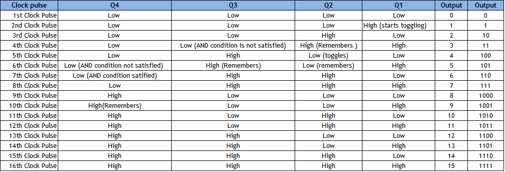
The below table shows the outputs of 4 flip flops Q1, Q2, Q3, Q4.The first flip-flop toggles on every edge triggered pulse .While the second one triggers only if its inputs are high at a given clock pulse. The third flip-flop toggles if the two ouputs Q1 and Q2 are high. Similarly, Q4 will toggle if all the three Q1,Q2,Q3 are high.
After reaching zero again the three flip flops toggles to logic low i.e 0000 and again count starts.
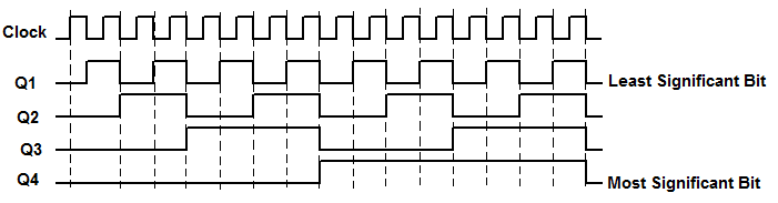
Timing diagram for up counter is shown below.
4 bit Synchronous DOWN Counter
Down counter counts the numbers in decreasing order. This is similar to an up counter but is should decrease its count. So inputs of JK flip- flop are connected to the inverted Q (Q’) .The 4 bit down counter shown in below diagram is designed by using JK flip flop. The same external clock pulse is connected to all the flip flops.
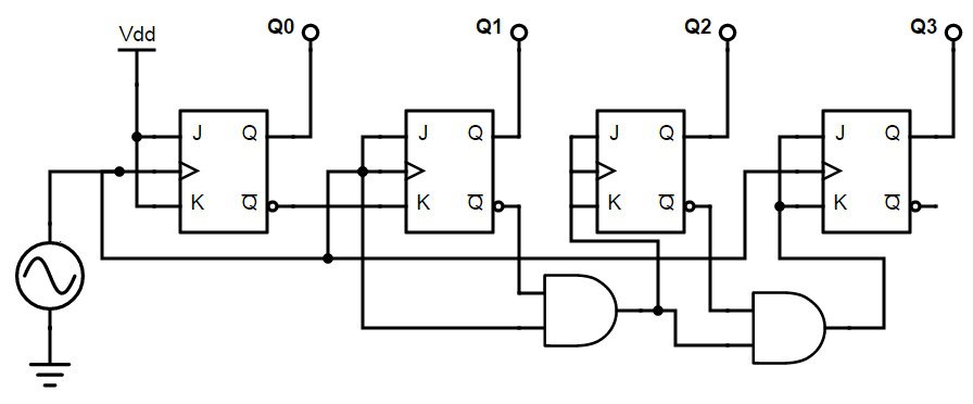
As the counter has to count down the sequence, initially all the inputs will be in high state as they have to count down the sequence. It will start with 1111 and ends with 0000, similar to the up counter.
In the down counter it should be remembered that, preceding flip flop will toggles only if front flip flop produces low logic at its output.
4 bit Synchronous Up/Down Counter
The above two counters can be implemented in a single counter called up down counter.This can be selected from its input. The design of up/ down counter with JK flip flops is shown below.
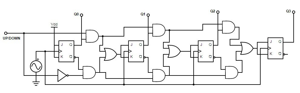
The up/ down counter has “Up” and “Down” count modes by having 2 input AND gates, which are used to detect the appropriate bit conditions for counting operation. OR gates are used to combine the outputs of AND gate, from each JK flip flop.
We provide a up/ down control line which enables upper or lower series of AND gates to pass the outputs of JK flip flops, Q , Q’ to the next stage of flip flop, in the cascaded arrangement.
If the up /down control line is set to HIGH, then the top AND gates are in enable state and the circuit acts as UP counter. If the up /down control line is set to low, then the bottom AND gates are in enable state and the circuit acts as DOWN counter.
Applications of Synchronous Counters
The most common and well known application of synchronous counters is machine motion control, the process in which the rotary shaft encoders convert the mechanical pulses into electric pulses. These pulses will act as clock input of the up/ down counter and will initiate the circuit motion.
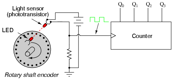
This circuit consists of photo transistor or light sensor and a LED connected to the rotor shaft. This arrangement is connected to the UP/ DOWN counter. When the machine started to move, it turns the encoder shaft by connecting and disturbing (making and breaking) the light beam between the light sensor and LED.
By this motion, the rotor creates clock pulses to increase the count of the up/ down counter circuit. So the counter note downs the motion of the shaft and gives the value that how much distance the rotor has moved.
To count the motion of the rotor shaft we increment the count by moving shaft in one direction and decrement the count by moving in another direction. We also use an encoder /decoder circuit to differentiate the direction of motion.

2 Responses
Excellent notes
Your note is very nice and it is very helpful