Today we are going to make a simple clap switch, how to switch on the lights, for a while, with a single clap. This will help us to search some objects in the dark, when you are watching TV or lying on bed etc.
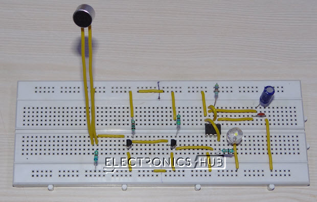
How To Make Simple Clap Switch: Circuit, Working?
Components Required
- 1-mic
- 1k
- 4.7k
- BC547 X2
- 470R
- 0.1uf X2
- 47k
- 100uf
- 330R
- 555 timers
- led
- 9v battery
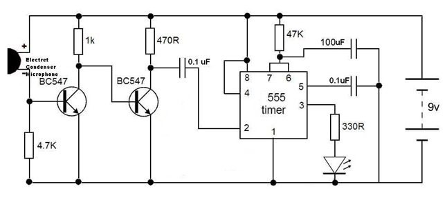
Circuit Diagram
What is 555 Timer???
Basically, 555 timer is an 8-pin integrated chip which has capable of producing accurate time delays or oscillation. By connecting different values of resistor and capacitor to a 555 timer we can use it for countless applications.
In simple, it was operating in 3 different modes
- Astable
- Monostable
- Bistable
Astable State
“Here the output pulse was continuously switches the state(high – low).”
Once we power up the circuit, there is no stable state in the output. Means, it will oscillate at a particular frequency depending upon the RC (resistor – capacitor) values connected with the 555 timer.
Either we can increase or decrease the frequency by changing RC values.
Monostable state
“for a single low trigger input, the output pulse goes to high (we can increase or decrease the ‘high state’ time )and come back to low. “
In simple, its an one pulse mode. By default the output of this circuit will be low (‘0’). when we give a low signal to a trigger pin.
The output will goes to high (‘1’) for a certain time and it will come back to the low state. The time for which the output stays high can be controlled by a suitable RC values.
Bistable state
“ It is possible to set the output either high or low, by providing low values for a particular ‘ TRIGGER’ or ‘ RESET ‘ pin.”
in this circuit, we have two switches called ‘ TRIGGER’ and ‘ RESET ‘.
Once the TRIGGER is set to LOW, the output will stays HIGH until the RESET set to LOW.
in simple,
TRIGGER == LOW –> OUTPUT = HIGH
RESET == LOW –> OUTPUT = LOW
TRIGGER==RESET==LOW –> OUTPUT =HIGH
Our aim is to switch on the light for a particular time..
so for this kind of application obviously we need to use MONOSTABLE mode.
How to
Get a monostable output using 555 timer???
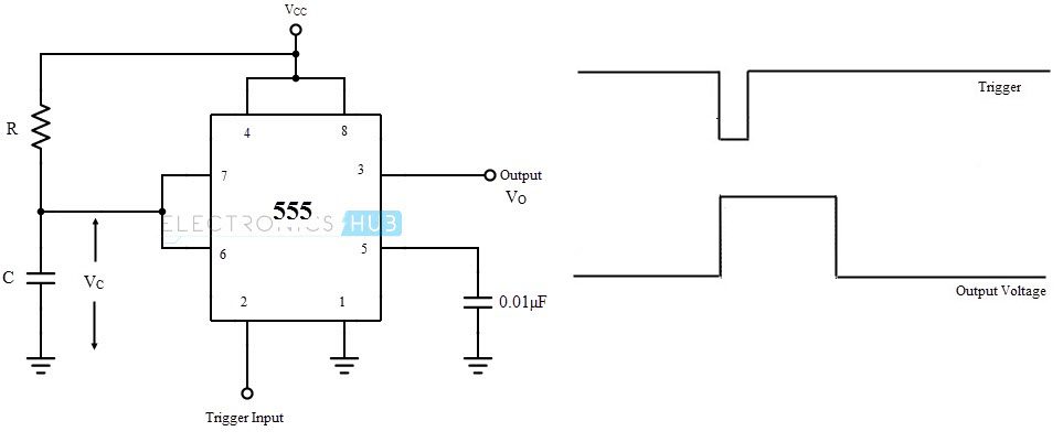
The above figure shows the connection of the 555 to get the monostable output. The values of the resistor R and the capacitor C decides how long the output pulse should stay high and time can be calculated using the following equation.
Time (secs) = 1.1 * R1 * C1
Where,
R – Resistance in ohms
C – Capacitance in farads
So, when we give a low input to the trigger pin ( pin 2). We can get the high output in the output pin (pin 3). According to the values of the resistor and capacitor the width of the output pulse will be increased or decreased.
For eg.,
R = 4.5k ohms
C = 1000uf
Time (secs) = 1.1 X (4.5 X 1000) X (1000 X 10 ^ -6)
= 4.95 secs
Means, the output pulse will stay high for 4.95 seconds. After 4.95 the pulse will come back to low state.
Working
Consider the above circuit into 2 parts, the job of the left part of this circuit is to give the low signal to the right part, which has 555 timer.
We already seen the right part of the circuit in “ how to get the monostable output using 555 timer “. According to that, all we have to do is to provide a low signal to the 555s TRIGGER pin (pin 2) to switch on the light for a desired time.
NOTE : By default T1 is on and T2 is off.
When we power up the circuit, the current will flow from source to the (+ve) mic and leaves at (-ve). Due to the low resistance of the mic the sufficient amount of current will flow to the base of T1. That current helps the T1 to turn on.
NOTE : the resistance of the mic will become HIGH when it detect the sound.
Due to this, the voltage across the collector-emitter of T1 is zero. So that no voltage across base-emitter of T2 that is the reason why the T2 is in off state by default.
When T2 is turned off the voltage across collector-emitter of T2 was almost equal to the source voltage. As discussed before trigger requires low signal to on the 555.
When the sound was detected by the mic the resistance of the mic will become high. Due to this, there is no current flow to the base of T1 which makes the T1 to turn OFF.
Due to this, the voltage across the collector-emitter of T1 was high, this makes the T2 to turn ON.
Once the T2 was in ON, the voltage across collector-emitter of T2 will be low. This LOW was sensed by the trigger pin (pin 2), which makes the 555 to produce the monostable output.

15 Responses
why we use relay
No relay is used in this circuit
Relay is nothing but it’s switch ……
can we use relay instead of LED to switch ON an ac 220V lamp?
Hi,
Yes. You can use a relay instead of the LED. But drive the relay with a Transistor and be careful with the AC Mains connections.
Which number transistor we can use for relay
Sir, How can I make this project as bistable output to ON OFF according to clap. How Output remain on until second clap .
Thank you ! It’s very good explanation
This is a very good circuit . This is a good project for beginner
I want to make the led off even for clap also, how can i make it, The led is in on state only for few seconds, but instead can we make it off for other clap also, How ??
Is there any way to increase the sensitivity of this circuit? I have trouble with triggering the timer from the mic. Please help me out. I need this piece of cake in my project and this is the last part that doesn’t work properly.
what is relay?
switching device
Very nice project !
This is such a cool project! I love how simple the circuit is, and I can’t wait to try making my own clap switch. The explanation of the working principle was really clear and helpful. Thanks for sharing!