The PSU of your desktop computer is one of its most important components. The power supply unit and the power supply cables connected to it are essential components of a personal computer that provide the necessary electrical power for all the hardware components to function. And if these are not compatible with the application or with the PSU, it will affect all of your components and their performance. Without a proper power supply, your GPU can also underperform and cause regulations on the display, such as stuttering or random freezes.
Therefore, buying the right PSU for your system is extremely important. The PSU ensures that the voltage supplied to the PC components remains stable and within the specified limits. Fluctuations or irregularities in voltage can damage sensitive components like the motherboard, processor, and storage devices. A reliable PSU provides consistent voltage regulation, safeguarding the components from potential harm.
And since almost all PSU choices on the market currently offer a modular design, you can also find a lot of similarly premium power supply cables for your unit. But before you choose a set of power cables for your PSU, you must carefully understand how to choose the perfect option. And for that, it is necessary to understand the overall construction and functioning of a PSU and how it can also be affected by your choice.
What is a Power Supply Unit, and How Does It Work?
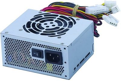 A power supply unit converts the incoming electrical power from an outlet into the appropriate voltage levels and delivers it to the components of the device. Its primary function is to provide a stable and reliable power source for the proper operation of the device.
So to find the most compatible option for a power supply cable set for your PSU, you should first understand how a PSU works. Electrical power supplied by utility companies is in the form of alternating current. However, electronic devices, including computers, require direct current to operate.
So, the PSU’s first task is to convert the AC power from the wall outlet into DC power that the computer can use. The PSU uses a transformer to step down the high voltage from the standard wall outlet to a lower, safer level. This lower voltage is typically around 12 volts. After the transformer, the PSU utilises a rectifier to convert the AC power into pulsating DC power. The rectifier allows current to flow in only one direction, effectively converting the AC waveform into a series of positive and negative voltage pulses.
The pulsating DC power produced by the rectifier still contains ripples or fluctuations. To remove these ripples and achieve a smoother DC output, the PSU incorporates capacitors that act as filters. Capacitors store electrical charge and release it during low-voltage periods, helping to smooth out the DC waveform. The filtered DC power may still vary slightly in voltage, which can harm sensitive electronic components. Voltage regulation circuits in the PSU ensure that the output voltage remains stable, within predefined limits, regardless of variations in the input voltage or load conditions. This stability is crucial for the proper functioning and longevity of the device.
Many modern PSUs have multiple output rails to power different components within the device. For example, a computer PSU may have separate rails for the motherboard, graphics card, storage devices, and peripherals. Each rail is designed to deliver the appropriate voltage and current for the specific components it powers. PSUs incorporate various safety features to protect the device and its components. These features include over-voltage protection (OVP), under-voltage protection (UVP), short-circuit protection (SCP), over-current protection (OCP), and over-temperature protection (OTP). These protections safeguard against voltage spikes, insufficient power, short circuits, excessive current draw, and overheating.
How To Connect Power Supply Cables?
Now that you understand the construction and working of a PSU, let us move on to the cables. This section will discuss how you can connect the power supply cables to your system. Apart from that, you should also know which cables are designed for what component.
Connecting power supply cables may vary depending on the specific device or system you are working with. However, the general steps to connect power supply cables in a desktop computer are pretty much the same.
1. Connection to (24-pin)
The largest connector of the power cable set, the 24-pin power connector, is one of the most important cables since it provides power to your motherboard. Without that, the motherboard won’t be booted up, causing the entire system to fail. Unlike older motherboards with a 20-pin connector, you will need a 24-pin power supply for almost all new-gen options.
As there are a lot of pins, connecting a 24-pin connector might be a bit tougher than you think. We recommend putting in the smaller (4-pin) first, then that pug in the 20-pin connector. This allows you to keep the more extensive section perfectly level at the time of insertion. Once the pin is fully inserted, it should look like a single cable, ensuring proper connection. Also, remember that the pins on a 24-pin connector are keyed and clipped. So if misaligned, forcing the pins can permanently damage your motherboard.
2. Connection to (8 (4+4) pin)
The 8-pin or 4+4-pin connector of a power supply cable set is designed to supply power to the CPU. And since the CPU is also one of the core components of your system, you should be very careful when connecting this pin. As there are a lot of models available on the market right now for CPUs, motherboard manufacturers have also designed different socket designs to serve the requirements of the CPU. Right now, you can find a 4-pin, 8-pin, 8+4 pin, or even an 8+8-pin. While the later options are usually available on high-end motherboards designed for overclocking, you will mostly find a 4+4 pin on a standard motherboard.
3. Connection to (6/8 pin)
A 6/8 pin motherboard typically refers to the power connectors used to supply power to the CPU on a computer motherboard. These connectors are often called EPS (Extra Power Supply) connectors. A standard 8-pin EPS connector consists of two separate 4-pin connectors that can be joined together to form an 8-pin connector. This provides additional power to the CPU, ensuring stable and reliable operation, particularly for high-performance processors.
Sometimes, a motherboard may only require a 6-pin EPS connector instead of the full 8-pin connector. This is often found on lower-power or budget-oriented motherboards with lower CPU power requirements. It’s worth noting that the specific power connector requirements can vary depending on the motherboard and CPU you’re using. It’s essential to consult the motherboard and CPU manuals or specifications to determine the correct power connectors needed for your system.
4. Connection to (4-pin) Molex Connectors
A 4-pin Molex connector, also known as a Peripheral connector, is a type of power connector commonly used in computer systems. It was widely used in older systems but has become less common in modern systems as technologies have evolved. The 4-pin Molex connector features a square-shaped plastic housing with four pins arranged in a rectangular pattern. It provides both power and voltage to various components such as hard drives, optical drives, fans, and other peripherals. The connector is designed to ensure a secure and reliable connection.
The pins of a 4-pin Molex connector are typically labelled as +12V, +5V, and two grounds (GND). The +12V and +5V pins provide the necessary power to the connected devices while the grounds complete the electrical circuit. This connector type can deliver 12 volts and 5 volts of DC power. It’s important to note that while 4-pin Molex connectors were once widely used, their usage has decreased due to the popularity of Serial ATA (SATA) connectors for powering storage devices and the adoption of more efficient power connectors. However, you may still find 4-pin Molex connectors in older power supplies and components or as part of adapters or converters for legacy devices.
5. Connection to SATA Cable
A SATA (Serial ATA) cable connects storage devices to a motherboard, such as hard drives and solid-state drives (SSDs). SATA cables transmit data and provide power to the connected storage devices.
SATA cables have a small L-shaped connector on each end. One end connects to the SATA port on the motherboard, and the other end connects to the SATA port on the storage device. The connectors are designed to fit securely and prevent accidental disconnection. Modern motherboards typically have multiple SATA ports, allowing you to connect multiple storage devices simultaneously. The number of SATA ports can vary depending on the motherboard model, ranging from four to ten or more. Each SATA port is usually labelled with a number or a name (e.g., SATA0, SATA1, SATA2, etc.) for identification.
When connecting a SATA cable to a motherboard, it’s important to align the connectors correctly to ensure a proper connection. The L-shaped connector on the cable should match the L-shaped slot on the motherboard’s SATA port. SATA cables are widely used in modern computer systems and are a standard method for connecting storage devices to motherboards.
6. Connection to (3-pin)
A 3-pin fan adapter is a cable used to connect a computer fan to a motherboard header. The adapter typically has a 3-pin female connector on one end and a 3-pin male connector on the other end. The 3-pin fan connector is a common type of connector used for computer fans. It consists of three pins that provide power, ground and a tachometer (RPM) signal. When connected to a motherboard header, the fan can receive power from the motherboard and send the tachometer signal to monitor the fan speed.
To connect a fan to a motherboard, you would typically align the 3-pin female connector on the fan adapter with the corresponding 3-pin male connector on the motherboard header. The connector on the motherboard header is usually labelled as “CHA_FAN” or “SYS_FAN” (short for chassis fan or system fan), along with a number indicating the fan header’s specific location (e.g., CHA_FAN1, SYS_FAN2). It’s important to note that 3-pin fan connectors provide basic functionality, such as power and monitoring fan speed. However, they do not support advanced features like fan speed control or PWM (Pulse Width Modulation) control. For fans that support these features, you would need to use a 4-pin PWM fan header on the motherboard or an appropriate adapter.
7. Connection to (6-pin)
A 6-pin PCIe connector on a motherboard typically provides additional power to PCI Express expansion cards, such as graphics cards or other high-power devices. The connector is designed to deliver extra power beyond what can be supplied through the PCIe slot alone.
The 6-pin PCIe connector consists of a six-pin male connector on one end and is typically connected to a corresponding female connector on the graphics card or other PCIe device. The purpose of the 6-pin PCIe connector is to ensure that the PCIe device’s power demands are adequately met. High-performance graphics cards, for example, can draw significant power, and the PCIe slot alone may not provide sufficient power to operate them reliably. The additional power provided through the 6-pin PCIe connector helps to ensure stable operation.
8. Connection to (4-pin)
The 4-pin floppy drive connector, also known as the Berg connector, was used in older computer systems to connect floppy disk drives to the motherboard. However, this connector has become obsolete in modern systems as floppy drives are no longer commonly used. The 4-pin floppy drive connector consists of a 4-pin female connector on the floppy drive cable and a corresponding 4-pin male connector on the motherboard. It provided both power and data connections for the floppy drive.
The connector was labelled as “Floppy” or “FDD” on the motherboard and was typically located near the IDE or SATA ports. The floppy drive cable had a twisted section that allowed for the proper orientation of the connector on the motherboard. Since floppy drives are rarely found in modern systems, most newer motherboards do not include a floppy drive connector. Instead, they allocate resources and connectors for more contemporary storage devices such as hard drives, SSDs, and optical drives.
Power Supply Cable – FAQs
Ans: To determine the cables you need for your power supply, first, identify the make and model of your power supply unit and check its specifications to see the types and quantities of connectors available. Assess your system’s components and their power requirements, then match them to the available connectors on your PSU. You should also consider adapters or additional cables if necessary, and ensure the cable lengths suit your system’s layout. If unsure, consult the PSU’s manual or the manufacturer for specific cable information.
Ans: The size of the power cable you need depends on the voltage and current requirements of your device. Ensure that the power cable matches the voltage rating (e.g., 110-120 V or 220-240 V) and has a current rating that meets or exceeds your device’s requirements. Additionally, consider the plug type needed for your device and choose a cable length suitable for the distance between your device and the power source. Consulting your device’s documentation or contacting the manufacturer can provide specific guidance on the correct power cable size.
Ans: Yes, it does matter what power supply cable you use. The correct power supply cable designed for your specific device and power supply is crucial for ensuring compatibility, safety, and optimal performance. Using an incorrect or incompatible power supply cable can lead to electrical issues, overheating, or even damage to your device or power supply. Always use cables that are specifically designed for your power supply and follow the manufacturer’s recommendations to ensure safe and reliable operation.
Ans: The number of pins a PSU (Power Supply Unit) should have depends on the specific PSU model and its compatibility with the motherboard. The most common PSU connector is the 24-pin ATX connector, which provides power to the motherboard. Additionally, PSUs may have additional connectors such as 4-pin or 8-pin EPS connectors for CPU power, PCIe connectors for graphics cards, SATA connectors for storage drives, and Molex connectors for peripherals. The exact number and types of connectors required for a PSU depend on the components in your system and their power requirements. It is important to check the motherboard and component specifications to determine the appropriate number and type of connectors needed for your PSU.
Conclusion
A Power Supply Unit (PSU) is a critical computer system component that converts electrical power from the wall outlet into usable power for the internal components. It supplies the necessary voltages and currents to ensure proper operation of the CPU, graphics card, storage devices, and other components. Different components and devices require specific power connectors.
Using the correct cables ensures the power supply can properly deliver power to each component without compatibility issues. Incorrect cables may not fit or deliver the required power, potentially causing damage to the components or PSU. Choosing the right power supply cables is essential for the safe and reliable operation of your computer system. It ensures compatibility, safety, optimal performance, and energy efficiency and maintains warranty coverage.
