Audio mixing is the process of combining multiple audio channels into one or more audio channels. In this process source signals, frequency content, dynamics, level and panoramic position are manipulated. This audio mixing process is used in sound recording in order to produce the output which is more appeal to listeners.
This audio mixing is also done in studios in order to produce album or single. Generally audio mixing process is carried out by the mixing engineer. Currently artists and engineers are using PC (personal computer) for audio mixing. This article describes you how to design a multi channel audio mixer using lm3900 quad amplifier. This audio mixing circuit has 2 MIC inputs and 2 line inputs. If you want to increase the input channels according to the application then add same circuit in parallel with the existing circuit. Before going to know about this circuit, get an idea about how simple audio tone control circuit works.
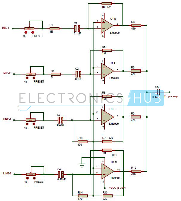
Circuit Diagram of Multi Channel Audio Mixer using LM3900:
Circuit Components:
- LM3900 Quad operational amplifier
- 1k PRESET – 4
- MICs – 2
- 0.47uF Electrolytic capacitor – 2
- 0.1uF Electrolytic capacitor – 2
- 0.1uF capacitor – 1
- 1Ω Resistor (1/4 watt) – 2
- 1M ohm resistor (1/4 watt) – 4
- 470 ohm resistors (1/4 watt) – 6
- 330 ohm resistors (1/4 watt) – 2
- Connecting wires.
- Power supply circuit
Multi Channel Audio Mixer using LM3900 Circuit Design:
The main component in this circuit is lm3900 quad operational amplifier. Each input channel of audio mixer is connected the inverting terminal of op amp. The operational amplifier of each stage amplifies the every input signal separately. The output of each op amp is given to single output line with resistance of 470 ohm. This circuit does not have low input impedance to mix ideal audio input channels. Here polarized capacitors C1 to C4 are connected to the input channels used for decoupling purpose. Capacitor C5 is the decoupling capacitor at the output. Here variable resistor is connected to each input channel. This variable resistor is used to adjust the volume of corresponding input channel.
Related Post: Audio Equalizer Circuit using Combinational Logic Gates
LM3900 Quad Operational Amplifier:
This IC consist of 4 high gain, independent, frequency compensated Norton amplifiers. These operational amplifiers are designed to operate for wide range of voltages. These amplifiers provide good response for almost all signal frequencies. This IC is able to provide wide band width and large output voltage swing. This IC has Inbuilt short-circuit protection.

Pin Description:
- 1IN+: Non – Inverting terminal of first operational amplifier.
- 2IN+: Non – Inverting terminal of second operational amplifier.
- 2IN-: Inverting terminal of second operational amplifier.
- 2OUT: Output terminal of second op amp.
- 1OUT: Output terminal of first op amp.
- 1IN-: Inverting terminal of first operational amplifier.
- GND: Ground pin.
- 3IN-: Inverting terminal of third op amp.
- 3OUT: Output terminal of third op amp.
- 4OUT: Output terminal of 4th op amp.
- 4IN-: Inverting terminal of fourth operational amplifier.
- 4IN+: Non-Inverting terminal of fourth operational amplifier.
- 3IN+: Non-Inverting terminal of 3rd operational amplifier.
- VCC: At this we can apply voltage from 4.5 to 32V.
To know more details about LM3900 IC, refer LM3900 Datasheet.
This audio mixer circuit can be powered between 5 to 30V. If the supply circuit is far from audio mixer circuit then connect a 100uF/60V capacitor between supply and ground pins.
Multi Channel Audio Mixer Circuit Features:
- Wide supply voltage range
- Low input current (30nA)
- Open loop gain is very high
- simple design
- Good frequency response
- Low noise
- Output short circuit protection
How to Operate Multi Channel Audio Mixer Circuit using LM3900?
- Initially give the connections as per the circuit diagram.
- While giving the power supply, make sure that output is well regulated.
- Now give the audio inputs.
- At the output of audio mixer you will get mixed audio signal.
Multi Channel Audio Mixer Circuit Applications:
- This audio mixer is used in sound recording to produce the audio which is more appeal to the listeners.
- Used in studios to produce album.
Limitations of the Circuit:
This circuit is studied theoretically and may require some changes to implement it in practical.

3 Responses
Sir, I have been taken to prepare a Circuit Diagram of Multi Channel Audio Mixer using LM3900. I purchased all the items as mentioned above except
Power supply circuit. Retailer asked me the capacity of said circuit board like as Volt, Amp. So i could not purchased the said items.
You are requested to intimate Volt, Amp,etc of the Power supply circuit so that i can be purchased from retailer. Thanking you,
WHAT INPUT HAS TO BE GIVEN AT LINE 1 AND LINE 2 PLEASE REPLY SOON
hi every one if any know where can i buy complete project like PCB and all parts of LM 3900 so please gv the link