A monostable multivibrator using a 555 timer is a circuit that generates a single output pulse of a defined duration in response to an input trigger. This configuration of the 555 timer is also known as a one-shot multivibrator because it returns to its stable state after a single pulse. The duration of the output pulse is determined by an RC (resistor-capacitor) network connected to the timer. These guides cover everything from the basic principles, circuit diagrams, and practical assembly tips, to applications of the monostable multivibrator using the 555 timer.
Circuit and Operation
The following figure is the schematic of IC 555 as a Monostable Multivibrator. This is the basic mode of operation of the IC 555. It requires only two extra components to make it work as a monostable multivibrator: a resistor and a capacitor.
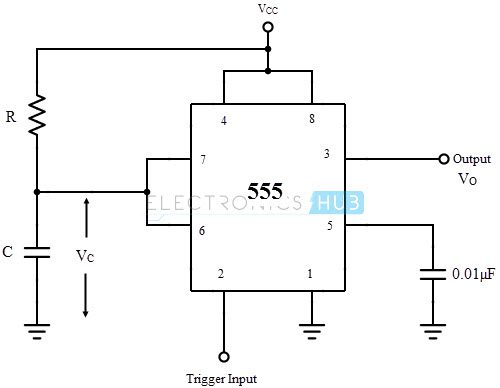
As the name specifies, a monostable multivibrator has only one stable state. When a trigger input is applied, a pulse is produced at the output and returns back to the stable state after a time interval. The duration of time for which the pulse is high will depend on the timing circuit that comprises of a resistor (R) and a capacitor (C).
The details of the connection are as follows. The pins 1 and 8 are connected to ground and supply (VCC) respectively. Output is taken at pin 3. To avoid accidental reset of the circuit, pin 4 is connected to the VCC. Pin 5, which is the control voltage input, should be grounded when not in use. To filter the noise, it is connected to the ground via a small capacitor of capacitance 0.01µF.
Operation
The monostable mode is also called “one-shot” pulse generator. The sequence of events starts when a negative going trigger pulse is applied to the trigger comparator. When this trigger comparator senses the short negative going trigger pulse to be just below the reference voltage (1/3 VCC), the device triggers and the output goes HIGH.
The discharge transistor is turned OFF and the capacitor C that is externally connected to its collector will start charging to the max value through the resistor R. The HIGH output pulse ends when the charge on the capacitor reaches 2/3 VCC. The internal connection of the IC 555 in monostable mode along with the RC timing circuit is shown below.
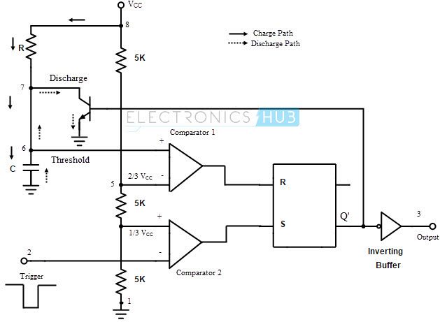
The detailed operation can be explained as follows. Initially, the flip-flop is RESET. This will allow the discharge transistor to go to saturation. The capacitor C, which is connected to the open collector (drain in case of CMOS) of the transistor, is provided with a discharge path. Hence the capacitor discharges completely and the voltage across it is 0. The output at pin 3 is low (0).
When a negative going trigger pulse input is applied to the trigger comparator (comparator 2), it is compared with a reference voltage of 1/3 VCC. The output remains low until the trigger input is greater than the reference voltage. The moment trigger voltage goes below 1/3 VCC, the output of comparator goes high and this will SET the flip-flop. Hence the output at pin 3 will become high.
At the same time, the discharge transistor is turned OFF and the capacitor C will begin to charge and the voltage across it rises exponentially. This is nothing but the threshold voltage at pin 6. This is given to the comparator 1 along with a reference voltage of 2/3 VCC. The output at pin 3 will remain HIGH until the voltage across the capacitor reaches 2/3 VCC.
The instance at which the threshold voltage (which is nothing but the voltage across the capacitor) becomes more than the reference voltage, the output of the comparator 1 goes high. This will RESET the flip-flop and hence the output at pin 3 will fall to low (logic 0) i.e. the output returns to its stable state. As the output is low, the discharge transistor is driven to saturation and the capacitor will completely discharge.
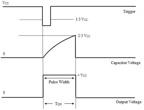
Hence it can be noted that the output at pin 3 is low at start, when the trigger becomes less than 1/3 VCC the output at pin 3 goes high and when the threshold voltage is greater than 2/3 VCC the output becomes low until the occurrence of next trigger pulse. A rectangular pulse is produced at the output. The time for which the output stays high or the width of the rectangular pulse is controlled by the timing circuit i.e. the charging time of the capacitor which depends on the time constant RC.
Pulse Width Derivation
We know that the voltage across the capacitor C rises exponentially. Hence the equation for the capacitor voltage VC can be written as
VC = VCC (1 – e-t/RC)
When the capacitor voltage is 2/3 VCC, then
2/3 VCC = VCC (1 – e-t/RC)
2/3 = 1 – e-t/RC
e-t/RC = 1/3
– t/RC = ln (1/3)
– t/RC = -1.098
t = 1.098 RC
∴ t ≈ 1.1 RC
The pulse width of the output rectangular pulse is W = 1.1 RC.
The waveforms of the monostable operation are shown below.
Applications of Monostable Multivibrator
Frequency Divider
When the IC 555 is used as a monostable multivibrator, a positive going rectangular pulse is available at the output when a negative going pulse of short duration is applied at the trigger input. By adjusting the time interval t of the charging or timing circuit the device can be made to work as a Frequency Divider circuit.
If the timing interval t is made slightly larger than the time period of the input pulse (trigger pulse), the device can act as a Divide – by – two circuit. The timing interval can be controlled by appropriately choosing the values of the resistor R and the capacitor C in the timing circuit. The waveforms of the input and output signals corresponding to the divide–by–two circuit are shown below.
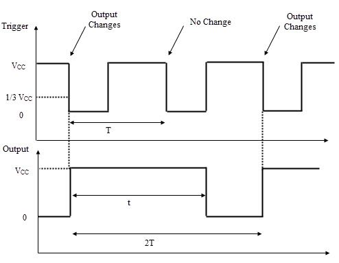
The circuit will trigger for the first negative pulse of the trigger input. As a result, the output will go to high state. The output will remain high for the time interval t. During this interval, even if a second negative going trigger pulse is applied, the output will not be affected and continues to remain high as the timing interval is greater than the time period of the trigger pulse. On the third negative going trigger pulse, the circuit is retriggered.
So the circuit will trigger on every alternate negative going trigger pulse i.e. there is one output pulse for every two input pulses and hence it is a divide–by–two circuit. By adjusting the timing interval, a monostable circuit can be made to produce integral fractions of the input frequency.
Pulse Width Modulation
The monostable mode of operation of the IC 555 can be turned into a Pulse Width Modulator by applying a modulating signal as the control voltage at the pin 5. The circuit for a Pulse Width Modulator using monostable multivibrator is shown below.
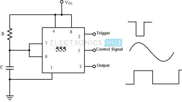
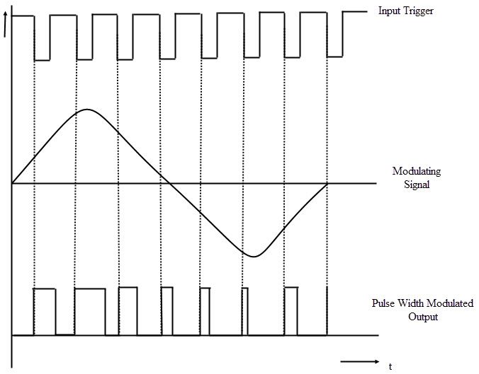
The control signal will modulate the threshold voltage and as a result, the output pulse width is modulated. As the control voltage varies, the threshold voltage; which is the input to the comparator 1, also varies. As a result, the time for charging the capacitor to the threshold voltage level will vary, resulting in a pulse width modulated wave at the output. The waveforms of the input, output and the modulating signal are shown below.
Due to the application of the control signal, the upper threshold voltage level for the capacitor will be different. The new upper threshold level UTL is given by
UTL = 2/3 VCC + VMOD
Where VMOD is the voltage of the modulating signal.
Because of the new threshold level, the pulse width of the output is given by
W = -RC ln (1 – UTL/VCC)
The time period of the output is same as the input.
Linear Ramp Generator
The monostable multivibrator will act as a Linear Ramp Generator with the addition of a constant current source. A current mirror, consisting of a diode and a PNP transistor, is used as a Constant Current Source. This constant current source is positioned in place of the timing resistor. The circuit for a linear ramp generator with IC 555 in monostable mode is shown below.
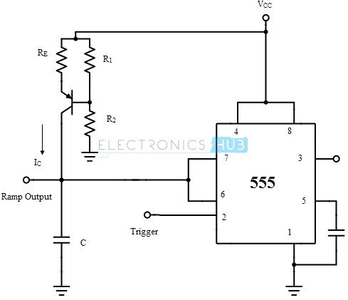
The current IC from the constant current source will charge the capacitor at a constant rate towards the peak voltage (VCC) resulting in a rising linear ramp. As the voltage across the capacitor reaches 2/3 VCC, the comparator 1 will drive the discharge transistor to saturation. As a result, the capacitor starts discharging. While discharging, as the voltage across the capacitor falls to 1/3 VCC, the comparator 2 will turn off the discharge capacitor.
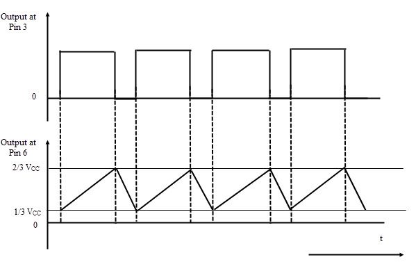
Hence the capacitor will start charging again. The discharge time of the capacitor is very less when compared to the charging time. As a result, the downward ramp is very steep (almost an immediate discharge). Hence, the time period of the ramp output is practically equal to the charging time of the capacitor. The time period of the ramp output is approximately given by
T = (2/(3 ) Vcc Re (R1+R2)C)/(R1 Vcc – Vbe (R1+R2))
The waveforms of the ramp output and the pulse output of a ramp generator are shown below.
Switching the Relay ON
The monostable multivibrator can be used to drive a relay. The circuit is shown below.
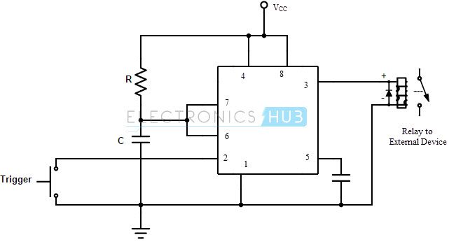
These circuits are called as Time Delay Relays. In this circuit, the relay will stay ON for a certain period of time once activated. This time, for which the relay is ON, can be anywhere between 0 to 20 sec depending on the values of R and C in the timing circuit.
For example, if the relay is to be ON for a period of 10s in order to energize an external device, then values of the resistor and the capacitor can be calculated as follows using the equation t = 1.1 RC.
By assuming the value of the capacitor to be its least possible value i.e. 10µF, the value of the resistor is
10 = 1.1 * R * 10µF
∴ R = 909090.9090 ≈ 909 KΩ.
A potentiometer can be used to adjust the resistance and therefore adjusting the time delay.
Missing Pulse Detector
The circuit of a Missing Pulse Detector is shown below. A PNP transistor is connected across the capacitor and the input trigger pulse train is given to the base terminal of the transistor as well as the pin 2 trigger input of the IC 555.
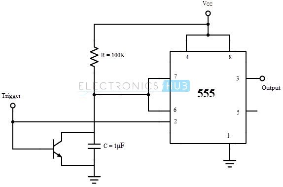
The train of trigger pulses will continuously reset the timing cycle. Hence the output is always high. If any trigger pulse is missing, the device detects this missing pulse and the output goes low. The detailed working is as follows. When the input is 0, the PNP transistor is turned ON and the voltage across the capacitor is clamped to 0.7 V and the output is HIGH. When the input trigger voltage is high, the transistor is cut-off and the capacitor will start charging.
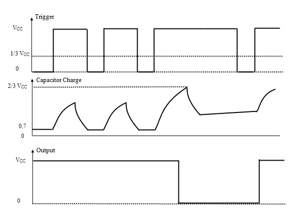
If the input trigger signal goes low again before the completion of the timing cycle, the voltage across the capacitor falls to 0.7 V before reaching the threshold voltage (2/3 VCC) and the output continues to remain HIGH. If the input trigger signal doesn’t go low before the completion of the timing cycle due to a missing pulse, it allows the capacitor to charge to the threshold voltage and the output will become LOW.
In order to make this circuit work as a Missing Pulse Detector, the time period of the input trigger signal should be slightly lesser than the timing interval. Because of this, the continuous negative going input pulses will not allow the capacitor to charge till the threshold voltage. And the output continues to stay high. In case of change of input frequency or a missing pulse, the capacitor will charge to the threshold voltage and the output falls low. The waveforms of the input pulse, voltage on the capacitor and the output signal are shown below.

One Response
I can’t figure out how to make a one shot that fires on the input but does not stay on even if the trigger stays on. In other words, if the monostable multivibrator (mvb) is triggered by a switch and the switch is held for 5 seconds the mvb outputs its pulse for however long the RC time is calculated for. I hope I’m making myself clear. These 555 multivibrators will continue the output pulse until the momentary switch is released. So, if you hold the switch down for three (3) seconds and the RC time is 0.5 seconds the 555 will continue the output pulse until the switch is released.