In this tutorial, we will see how to expand the Arduino UNO board’s IO capability with the help of PCF8574 IO Expander Board. By interfacing PCF8574 with Arduino UNO, you can increase the number of IO pins of your Arduino so that you don’t have to worry about connecting several IO devices like LEDs, LCD Display, Motors, Sensors etc.
Introduction
Arduino UNO has been the go-to board for beginners and hobbyists in electronics for implementing a wide range of applications. I have seen several projects developed using Arduino from simple motor control to complete weather stations with graphical OLED displays.
One of the main concerns with Arduino UNO is the number of Digital IO Pins available for using in our project. We know that Arduino UNO board comes with 13 Digital IO Pins and 5 Analog Input Pins.
For simple projects, this may be sufficient but if you want to develop a complex project with lots of sensors, a display unit (LCD or OLED), motor controls and communication (like Serial, which in turn takes away two IO pins), then you have to worry a little bit.
If you have an Arduino Mega board, then this won’t be an issue as you have a plethora of IO pins. The problem is only with smaller board like UNO and Nano.
To solve this problem, you can use the PCF8574 IO Expander Module. I have already used this IC to interface a 16×2 LCD Display with Arduino using just the I2C Pins. Check out that project here.
A Brief Note on PCF8574 IC
The PCF8574 is an I2C bus to 8-bot parallel bus IO expander IC. It provides GPIO expansion for many microcontrollers in a simple and cost-effective method. The interface for this IC is I2C (or I2C) using SDA (Data) and SCL (Clock) lines. So, if your microcontroller has a limited number of IO pins and has I2C capability, then you can use this IC to expand the IO pins.
The following is the pin diagram of PCF8574 IC in SOIC Package.
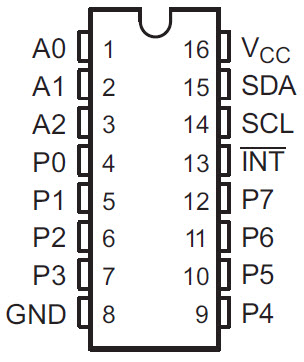
It has 16 pins in this package and the following table give a simple pin description.
Pin Number Description Address Inputs 4, 5, 6, 7, 9, 10, 11, 12 Input / Output Port 8 Ground 13 Interrupt Output (Must be pulled high to VCC) 14 Serial Clock of I2C (Must be pulled high to VCC) 15 Serial Data of I2C (Must be pulled high to VCC) 16 Voltage Supply
Pin Name
1, 2, 3
A0, A1, A2
P0 – P7
GND
INT
SCL
SDA
VCC
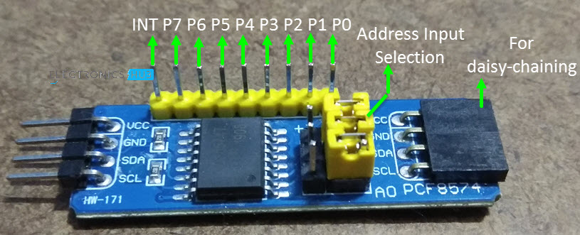
When you are shopping for PCF8574 IC based IO Expander Modules, you have to be careful as there are two types of boards available in the market using PCF8574 IC. One is a complete IO Expander Module with access to all the port pins, INT pin and the address pins. This module is shown in the following image. This is the module we are going to use in our project.
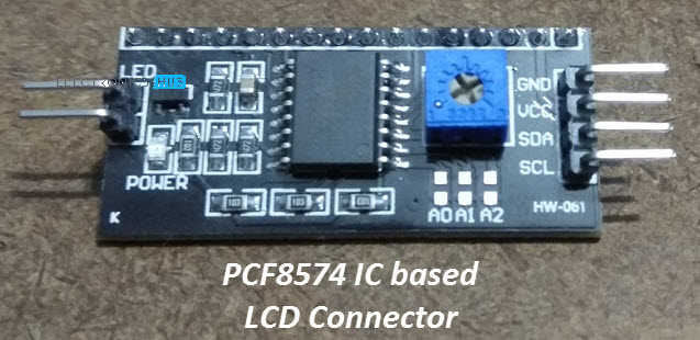
There is another board which is configured to be interfaced with 16×2 or 20×4 Character LCD Displays. In this board, the address pins are pulled HIGH and you don’t have access to all the IO pins and the INT pin. So, check twice before purchasing.
Interfacing PCF8574 with Arduino
Since the job of the PCF8574 Module is to expand the IO capabilities of a microcontroller, we can use it with our Arduino UNO board to increase the digital IO count to 21. The IO Port pins of the Module can be used as either input or output
The following is a simple block diagram of interfacing PCF8574 with a microcontroller where two of the IO Port pins are configured as inputs, one pin is to drive an LED and the remaining pins acts as control pins (outputs) for several external peripherals.
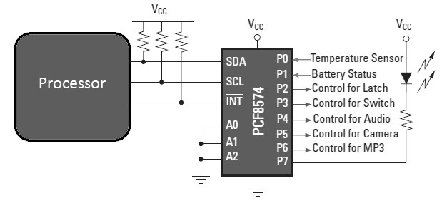
We can use a similar setup with our Arduino UNO board and PCF8574 IO Expander Board for controlling various peripherals.
Circuit Diagram
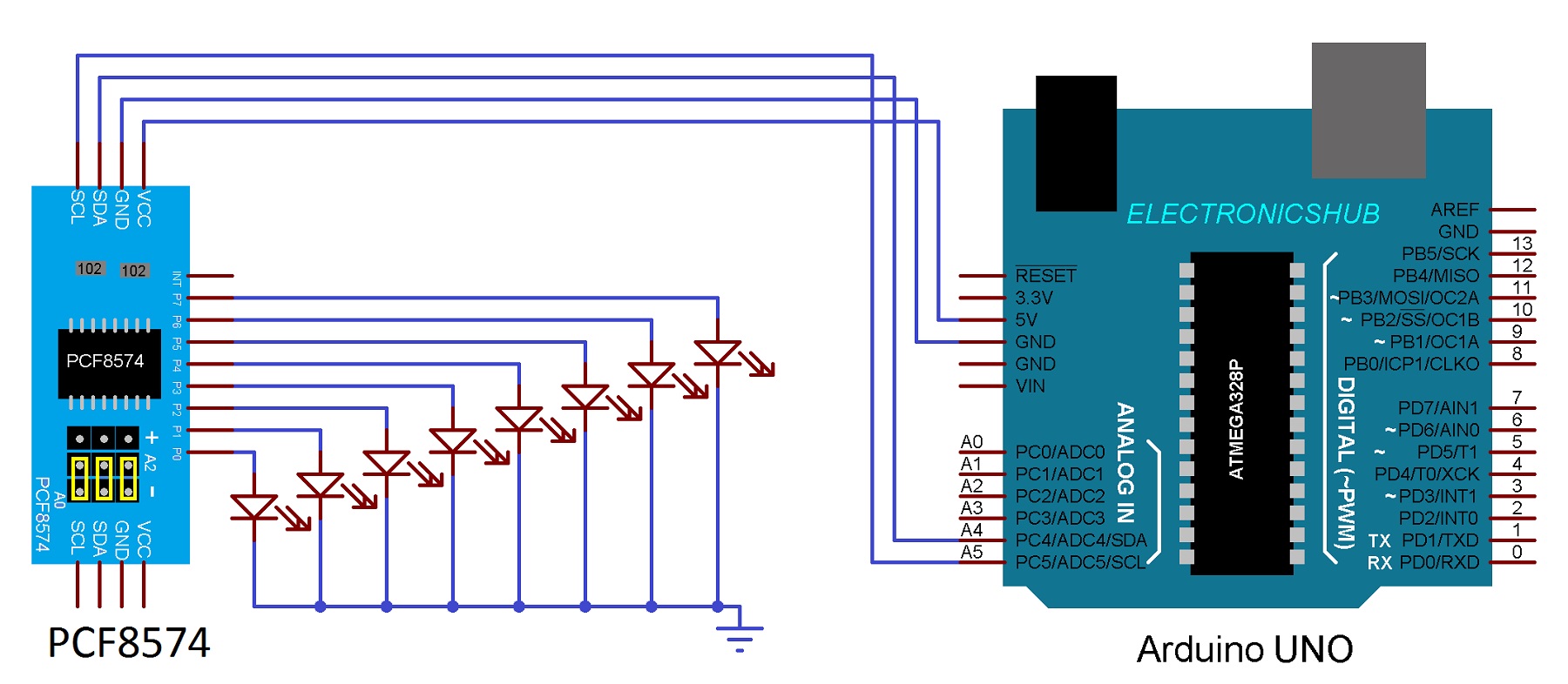
The following is the circuit diagram of interfacing PCF8574 with Arduino UNO board for controlling 8 LEDs.
Components Required
- Arduino UNO (or any Arduino Board)
- PCF8574 IO Expander Board
- Connecting Wires
- 5V Power Supply
- 8 x LEDs
- 8 x 330Ω Resistors
Connections Explained
Since PCF8574 Module works on I2C Communications, we have to use the I2C Pins of the Arduino to control the IO Pins of the module. Pins A4 and A5 of Arduino UNO are the I2C Pins where A4 is the SDA (Data) pin and A5 is the SCL (Clock) pins.
Connect these pins to the corresponding SDA and SCL Pins of the PCF8574 Board. Now, connect the VCC and GND Pins of the module to +5V and GND pins of the Arduino.
To test the project, let us connect some LEDs to the IO Port of the PCF8574 Module so that we can control them using our Arduino. So, connect 8 LEDs with corresponding current limiting resistors between VCC and the IO Port.
NOTE: I did not connect the series current limiting resistors in the circuit diagram. But I suggest you to connect them, just to be on the safe side.
NOTE: It is advised to use an external 5V power supply for the LEDs and not to power up the LEDs from the Arduino Board.
Code
For Resolving I2C Slave Address
First, we have to figure out the I2C bus slave address of the PCF8574 Module. Use the following code to calculate the address of the Module. In my case, when the A0, A1 and A2 pins are connected to LOW, the address turned out to be 0x20. So, I will be using this address in my actual code.
#include <Wire.h>
void setup()
{
Wire.begin();
Serial.begin(9600);
while (!Serial);
}
void loop()
{
byte error, address;
int I2CDevices;
Serial.println(“Scanning for I2C Devices…”);
I2CDevices = 0;
for (address = 1; address < 127; address++ )
{
Wire.beginTransmission(address);
error = Wire.endTransmission();
if (error == 0)
{
Serial.print(“I2C device found at address 0x”);
if (address < 16)
Serial.print(“0″);
Serial.print(address, HEX);
Serial.println(” !”);
I2CDevices++;
}
else if (error == 4)
{
Serial.print(“Unknown error at address 0x”);
if (address < 16)
Serial.print(“0”);
Serial.println(address, HEX);
}
}
if (I2CDevices == 0)
Serial.println(“No I2C devices found\n”);
else
Serial.println(“****\n”);
delay(5000);
}
For Controlling IO Port
Coming to the actual project, you don’t need any additional libraries apart from the “Wire” library, which comes with Arduino IDE. Use the following code to toggle alternate LEDs.
#include <Wire.h>
void setup()
{
Wire.begin();
}
void loop()
{
Wire.beginTransmission(0x20);
Wire.write(0xAA);
Wire.endTransmission();
delay(1000);
Wire.beginTransmission(PCF8574_ADDR);
Wire.write(0x55);
Wire.endTransmission();
delay(1000);
}
Working
The working of the project is very simple. I have interfaced the PCF8574 with Arduino using the I2C Communication. After determining the slave address of the PCF8574 Module, we have to begin the I2C Communication using this address.
As LEDs are connected to the IO port, all you have to do is to send different patterns of LED toggling codes in HEX format.
Since I2C doesn’t use any of the existing Digital IO pins of the Arduino, you get a total of 21 IO Pins on your Arduino UNO board (13 on Arduino UNO and 8 on PCF8574 IO Port), which you can use for a bigger project.
Summary
A simple project is implanted here where the number of IO Pins of an Arduino UNO Board are increased by interfacing PCF8574 with Arduino. Using this IO expander module, you can connect a number of IO devices like Temperature Sensor, Humidity Sensor, 16×2 LCD Display, Status LEDs, Relays, Motors etc. without worrying about the number of IO Pins.
