The CD4017 IC is a CMOS decade counter/decoder. It’s widely used in various applications due to its versatility and efficiency in counting operations. This integrated circuit is designed to count pulses. It has 10 fully decoded outputs, making it ideal for driving a 7-segment display or creating sequence timing applications in microcontroller projects.
The CD4017 is a CMOS Decade counter IC. CD4017 is used for low range counting applications. It can count from 0 to 10 (the decade count). The circuit designed by using this ic will save board space and also time required to design the circuit. CD4017 is as ‘Johnson 10 stage decade counter’.
CD 4017 IC-Decade Counter Features
- The supply voltage of this IC is 3V to 15V.
- It is compatible with TTL (Transistor -Transistor Logic).
- The clock speed or operational speed of CD4017 IC is 5 MHz.
This IC is also used in electronic industries, automotive industries, manufacturing medical electronic devices, alarms and in electronic instrumentation devices.
CD4017 Pin description
It has 16 I/O pins.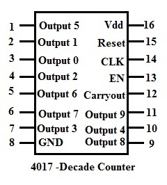
Output pins of CD4017(Pin 1 to 7 & 9 to 11)
- Pins 1 to 7 and 9 to 11 are outputs pins.
- These pins changes to ‘high’ level one by one (one after another) in a sequence. For each clock signal each pin goes high in a sequence.
Enable pin/Clock Inhibit(Pin 13)
- Enable pin enables the CD4017 IC.IC is enabled when the pin is active low.
- In order to disable or switch off the IC,this pin should be connected to active high input.When this pin is active high ,it ignores the clock signals.
Clock pin(pin 14)
- Clock signal provided to 14 th is responsible for sequential output.
- When the first clock pulse is detected pin 3 goes ,for next clock pulse pin2 goes high,like this sequence is formed.
- The important thing to remember is, if we don’t connect any clock signal to this input pin, it must be connected to either positive or negative voltage supply.
- It is not left unconnected as per the CMOS input standard rules.
- The clock input pin (pin number 14) responds only to the positive voltage signal or positive clock
Reset pin(Pin 15)
- Reset pin resets the output of the sequence.That is the current state of the output sequence is set to initial state.
- Reset pin should be connected to ground in order to reset the circuit.
Ground pin & supply pin(Pin 8 & Pin 16)
Pin number 8 acts as ground and it must be connected to negative supply voltage & pin number 16 is the supply pin for CD4017 and it is connected to positive voltage supply.
Carry out pin(pin12)
The pin 12 is supplied with the CARRY OUT signal. It completes one full cycle for every 10 clock cycles. This is used to ‘ripple’ the IC, which means to delay in counting operations.
Counting operation of CD4017 using waveforms
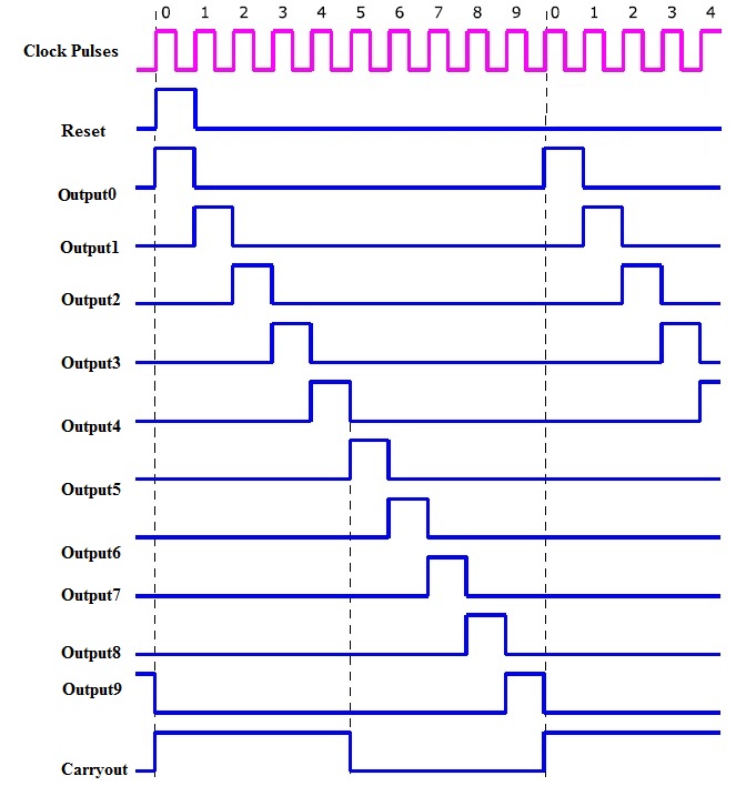
This is the timing diagram of the CD4017 with, shows us the comparison and also explains the counting sequence of the outputs, shifting from one pin to its next.
If we observe that, before applying the clock signal, the RESET is set to High, so the reset pin input sets all the output to their initial state.
Then the output of the first output pin 3 will be high. Next this output is shifted to its next output pin and this sequence continues till the next clock cycle.
Let us see some examples in which CD4017 is used.
Application of CD4017
LED Sequencer using 4017
The LED sequencer circuit by using CD4017 and IC 555 is shown below. This circuit is also called as “LED chaser circuit”.
Components
- CD4017 decade counter
- 555 timer IC
- Ten-segment bar graph LED
- switch and One 6 volt battery
- 1 MΩ resistor
- 0.1 µF capacitor
- Coupling capacitor, 0.047 to 0.001 µF
- 470 Ω resistors-10
Primarily it is important to remember that, as the CD4017 is a CMOS device, it is very sensitive to the static electricity.
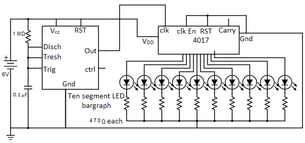
The LED sequencer circuit uses the 555 timer to produce the clock pulses required for CD4017, which is operated in Astable mode. Output of this Astable timer circuit is connected to the clock signal input of CD4017.
It produces stream of pulses continuously, in which the each pulse increases the counter by 1. So thus each LED will light up and then off before turning on its next LED in the sequence.
LED sequencer working
- Led sequencer works on the principle of CD4017.
- Let us understand the working by starting with 555 timer.
- 555 timer is operated in astable mode.It produces clock pulses continuously to the decoder IC.The duration of this clock pulse can be calculated by using R and C value in the circuit.
- For each pulse the CD4017 increases the counter value.Thus each pin of the counter goes high in a sequence.
- LEds connected to the output pins of CD4017 ,thus glows in a sequence.
Note
In order to make the counter to count upto certain number ,the last sequence pin should be connected to reset.
For example,
If you want to glow only 5 leds in a sequence instead of 10,connect the pin 1 of the 4017 to its reset.Thus when 6th clock pulse arrives, reset button goes from high to low transition and resets the IC.
Here are some cirucits where CD 4017 is used

7 Responses
hello dear;
i’m going to my semister project on this title.however i unable to run its own circuit configuration on proteus 8 .pleas what shall i do give your hand!
I’m working on the last semester project using this decade counter. How can it restricted to count up-to two counts only. Please help
Connect Output 2 (pin 4) of 4017 IC to its reset Pin (pin 15).
nice thanks
Very Well and Detail Information Explained about 4017 counter ic.
Plz upload detailsto about ledto driver max7219
Only ONE led balast resitor is needed as only one led is on a ta time..