In this tutorial, we will learn about Potentiometers. We will see what is a potentiometer, its construction and symbol, its working, different types of potentiometers, application of potentiometer as Rheostat and Voltage Divider and also Potentiometer Taper.
What is a Potentiometer?
A Potentiometer or POT, is a three-terminal device with manually adjustable resistance using a movable contact. A potentiometer is a variable resistor with a sliding contact that can be adjusted to change the resistance between the contact and the terminals.
We all are familiar with Resistors. They are simple electrical devices which resist the flow of current in a circuit. Normal resistors usually have fixed resistance. But what if you want vary the resistance as per the needs of your application? This is where Potentiometers come into play.
POT typically has three terminals:
- Terminal 1: One end of the resistance element.
- Terminal 2: The other end of the resistance element.
- Terminal 3: The wiper or slider that can be moved to adjust the resistance between Terminal 1 and Terminal 3.
Different Types of Potentiometers
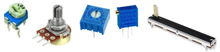
Even though the function is same, there are different types of Potentiometers available for various applications and use cases. Some of the popular types of POTs are mentioned below:
- Rotary POT
- Rheostat
- Single Turn POT
- Multi Turn POT
- Linear POT
- Dual Gang POT
- Servo POT
- Trimmer POT
- Concentric POT
- Preset POT
- Digital POT
- Membrane POT
- Trimmer POT
Potentiometers Symbols and Construction
Since they are essentially resistors but with variable resistance, the symbol of a potentiometer is also close to that of a resistor. The following image shows the symbol of a potentiometer.
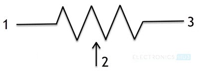
This symbol means a resistor with terminals 1 and 3 and sliding contact terminal 2. You will better understand this if we take a look at the construction of a typical potentiometer.
In rotating contact type potentiometers, there is a resistive track which is connected between terminals 1 and 3. A sliding contact, also known as Wiper, will move from end-to-end of the resistive track to vary the resistance.
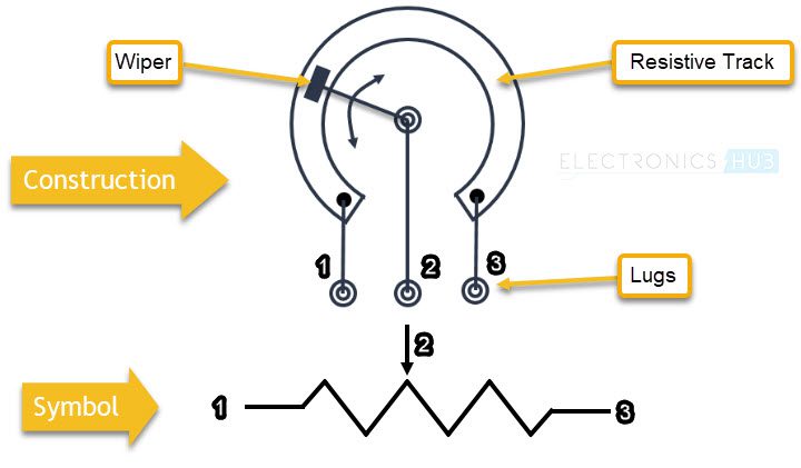
The external contacts are sometimes known as lugs.
Potentiometer Wiring: How Does Potentiometer Work?
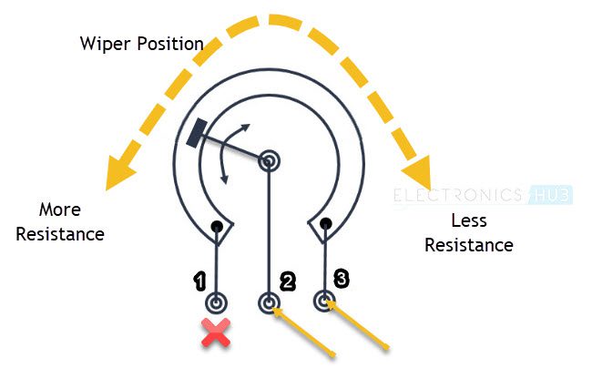
Let us now see how a potentiometer works. If you measure the resistance between the outer terminals, then you will always measure the maximum value (rated value) of that POT. For example, in case of a 10 KΩ POT, you will read full 10 KΩ between the outer terminals.
But, if you measure the resistance between one of the outer terminals and the Wiper terminal, then you will get a value that is dependent on the position of the Wiper. So, it can range from 0 KΩ to 10 KΩ in case of a 10 KΩ pot.
So, based on the terminals used, you can use the potentiometer as a simple Variable Resistor, also known as a Rheostat or a Voltage Divider.
Potentiometer Wiring Diagram
A potentiometer wiring has three terminals:
- Terminal 1 (A): One end of the resistive track.
- Terminal 2 (B): The wiper, which moves along the resistive track and varies the output voltage.
- Terminal 3 (C): The other end of the resistive track.
Terminal 1 (A) ———————+
|
R (Resistive Track)
|
Terminal 2 (B) —–(Wiper)———-+—- Output (Variable Voltage)
|
Terminal 3 (C) ——————— Ground or Reference Voltage
Rheostat Potentiometer Wiring Diagram
A Potentiometer can work as a Rheostat by making use of just two of its terminals: One is the Wiper and the other is either of the two outer terminals. In this case, the POT acts as a two terminal variable resistor.
The value of the resistance increases or decreases by turning the Wiper.
Voltage Divider Potentiometer Wiring Diagram
Another useful application of Potentiometers is they can be used as Voltage Dividers. If you remember, a Voltage Divider Circuit consists of two resistors connected in series. A voltage is applied at ends of the resistors and an output voltage is taken across a resistor.
This simple circuit is used to convert a high voltage to a low voltage. With the help of potentiometer, you can build a similar voltage divider by using all the three terminals.
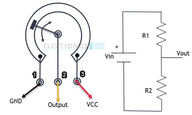
An input voltage is applied between the outer two terminals of the POT and the output voltage is taken between the wiper and the outer terminal which is connected to GND of the input supply.
Since a POT allows you to vary the resistance, you can essentially vary the output voltage of the Voltage Divider. Hence, this is a Voltage Divider with a variable output voltage.
For more information on voltage dividers, visit “VOLTAGE DIVIDER CIRCUIT“.
Potentiometer Taper
There are several characteristics of Potentiometers but one that stands out is called the Taper. This characteristic is the relation between the position of the Wiper and the amount of resistance.
Potentiometers are usually classified as in to two types based on the Taper characteristic. They are:
- Linear Taper
- Logarithmic Taper
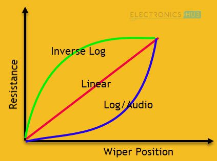
Linear Taper
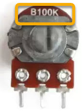
The most commonly found Potentiometers are of Linear Tapper type. In this type, the relation between the position of the Wiper and the resistance is linear. This type of POTs are usually marked with letter ‘B’.
Logarithmic Taper
Another common but very application specific POT is the Logarithmic Taper or Log Taper. They are also called as Audio Taper as they are essentially used in audio control applications (volume control).
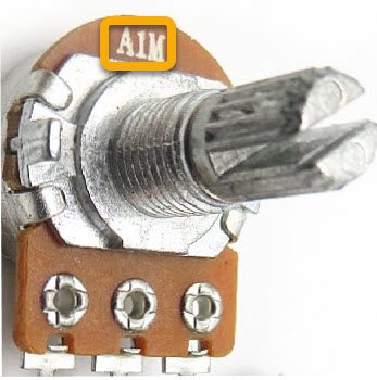
As the name suggests, in a log taper POT, the relation between resistance and wiper position is logarithmic. There are also Inverse Log Taper POTs. Log Taper POTs are usually marked with letter ‘A’.
How To Wire Potentiometer?
Below is a step-by-step guide for wiring a 3-terminal potentiometer, which is the most common type, for various applications:
POT Wiring Configuration:
You can wire a potentiometer in different ways depending on how you want to use it:
- Connect Terminal 1 to the positive terminal of your power source.
- Connect Terminal 2 to the negative terminal of your power source.
- Connect Terminal 3 to the load or component you want to control.
1. POT Wiring as a Voltage Divider: Wiring Steps
- Connect Terminal 1 (A) to the positive supply voltage (e.g., 5V, 12V, etc.).
- Connect Terminal 3 (C) to ground (0V).
- Connect Terminal 2 (B) (the wiper) to the output, which will give you the variable voltage between 0V and the supply voltage.
Voltage Divider Potentiometer Schematic
(A) Terminal 1 —- +V (Supply Voltage)
(B) Terminal 2 —- Output (Variable Voltage)
(C) Terminal 3 —- Ground (0V)
As you rotate or slide the potentiometer, the wiper moves along the resistive track, changing the output voltage from 0V to +V.
2. POT Wiring as a Rheostat: Wiring Steps
- Connect Terminal 1 (A) to one side of the circuit (e.g., the power supply or load).
- Connect Terminal 2 (B) (the wiper) to the other side of the circuit (e.g., the load or ground).
- Leave Terminal 3 (C) unconnected, or connect it to Terminal 1 (A) if needed for stability.
Rheostat Potentiometer Schematic
(A) Terminal 1 —- Load or Supply
(B) Terminal 2 —- Load or Ground
(C) Terminal 3 —- (Optional connection to Terminal 1 or left unconnected)
Here, the potentiometer adjusts resistance, which changes the current flow to the load.
Conclusion
A simple beginner’s tutorial on Potentiometers is presented here. You learned about some basics of Potentiometers, its working, electrical symbol and mechanical construction, two of the common applications and also different types.
