Heartbeat Sensor is an electronic device that is used to measure the heart rate i.e. speed of the heartbeat. Monitoring body temperature, heart rate and blood pressure are the basic things that we do in order to keep us healthy.
In order to measure the body temperature, we use thermometers and a sphygmomanometer to monitor the Arterial Pressure or Blood Pressure.
Heart Rate can be monitored in two ways: one way is to manually check the pulse either at wrists or neck and the other way is to use a Heartbeat Sensor.
In this project, we have designed a Heart Rate Monitor System using Arduino and Heartbeat Sensor. You can find the Principle of Heartbeat Sensor, working of the Heartbeat Sensor and Arduino based Heart Rate Monitoring System using a practical heartbeat Sensor.
Heartbeat Sensor using Arduino Output Video
Introduction to Heartbeat Sensor
Monitoring heart rate is very important for athletes, patients as it determines the condition of the heart (just heart rate). There are many ways to measure heart rate and the most precise one is using an Electrocardiography
But the more easy way to monitor the heart rate is to use a Heartbeat Sensor. It comes in different shapes and sizes and allows an instant way to measure the heartbeat.
Heartbeat Sensors are available in Wrist Watches (Smart Watches), Smart Phones, chest straps, etc. The heartbeat is measured in beats per minute or bpm, which indicates the number of times the heart is contracting or expanding in a minute.
Principle of Heartbeat Sensor
The principle behind the working of the Heartbeat Sensor is Photoplethysmograph. According to this principle, the changes in the volume of blood in an organ is measured by the changes in the intensity of the light passing through that organ.
Usually, the source of light in a heartbeat sensor would be an IR LED and the detector would be any Photo Detector like a Photo Diode, an LDR (Light Dependent Resistor) or a Photo Transistor.
With these two i.e. a light source and a detector, we can arrange them in two ways: A Transmissive Sensor and a Reflective Sensor.
In a Transmissive Sensor, the light source and the detector are place facing each other and the finger of the person must be placed in between the transmitter and receiver.
Reflective Sensor, on the other hand, has the light source and the detector adjacent to each other and the finger of the person must be placed in front of the sensor.
Here are few simple Arduino Projects: 10 SIMPLE ARDUINO PROJECTS FOR BEGINNERS.
Working of Heartbeat Sensor
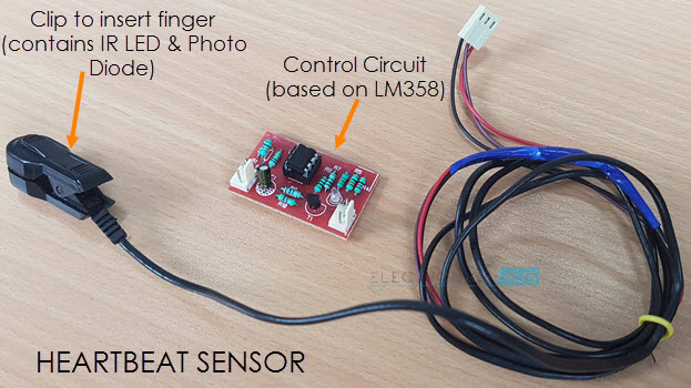
A simple Heartbeat Sensor consists of a sensor and a control circuit. The sensor part of the Heartbeat Sensor consists of an IR LED and a Photo Diode placed in a clip.
The Control Circuit consists of an Op-Amp IC and few other components that help in connecting the signal to a Microcontroller. The working of the Heartbeat Sensor can be understood better if we take a look at its circuit diagram.
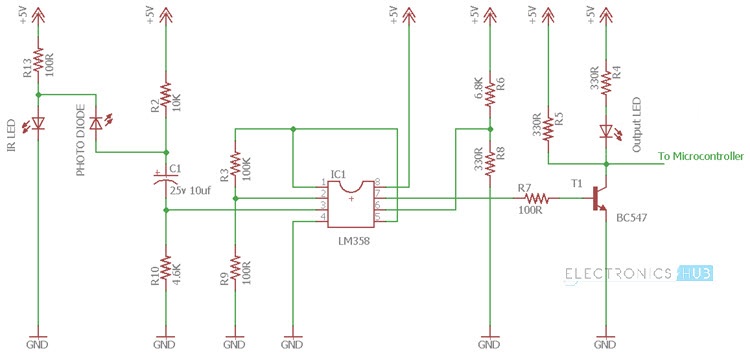
The above circuit shows the finger type heartbeat sensor, which works by detecting the pulses. Every heartbeat will alter the amount of blood in the finger and the light from the IR LED passing through the finger and thus detected by the Photo Diode will also vary.
The output of the photo diode is given to the non – inverting input of the first op – amp through a capacitor, which blocks the DC Components of the signal. The first op – amp cats as a non – inverting amplifier with an amplification factor of 1001.
The output of the first op – amp is given as one of the inputs to the second op – amp, which acts as a comparator. The output of the second op – amp triggers a transistor, from which, the signal is given to a Microcontroller like Arduino.
The Op – amp used in this circuit is LM358. It has two op – amps on the same chip. Also, the transistor used is a BC547. An LED, which is connected to transistor, will blink when the pulse is detected.
Circuit of Arduino based Heart Rate Monitor using Heartbeat Sensor
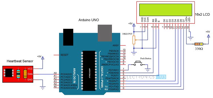
The following image shows the circuit diagram of the Arduino based Heart Rate Monitor using Heartbeat Sensor. The sensor has a clip to insert the finger and has three pins coming out of it for connecting VCC, GND and the Data.
Components Required
- Arduino UNO x 1 [Buy Here]
- 16 x 2 LCD Display x 1 [Buy Here]
- 10KΩ Potentiometer
- 330Ω Resistor (Optional – for LCD backlight)
- Push Button
- Heartbeat Sensor Module with Probe (finger based)
- Mini Breadboard
- Connecting Wires
Circuit Design of Interfacing Heartbeat Sensor with Arduino
The circuit design of Arduino based Heart rate monitor system using Heart beat Sensor is very simple. First, in order to display the heartbeat readings in bpm, we have to connect a 16×2 LCD Display to the Arduino UNO.
The 4 data pins of the LCD Module (D4, D5, D6 and D7) are connected to Pins 1, 1, 1 and 1 of the Arduino UNO. Also, a 10KΩ Potentiometer is connected to Pin 3 of LCD (contrast adjust pin). The RS and E (Pins 3 and 5) of the LCD are connected to Pins 1 and 1 of the Arduino UNO.
Next, connect the output of the Heartbeat Sensor Module to the Analog Input Pin (Pin 1) of Arduino.
Working of the Circuit
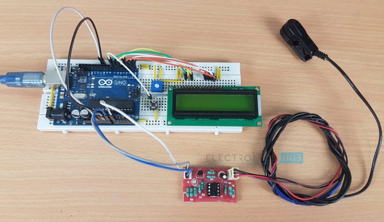
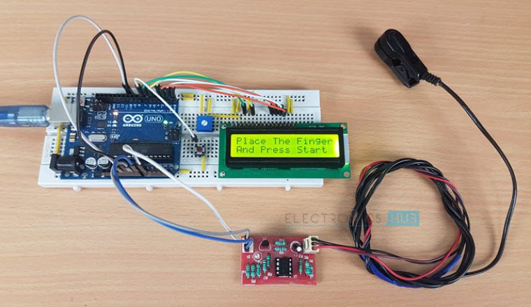
Upload the code to Arduino UNO and Power on the system. The Arduino asks us to place our finger in the sensor and press the switch.
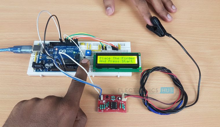
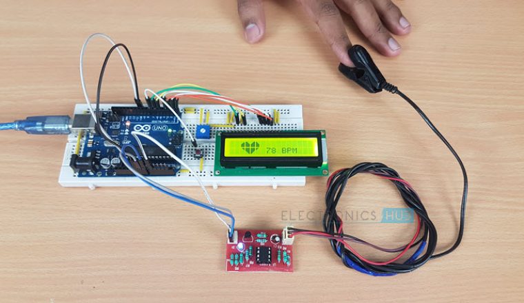
Place any finger (except the Thumb) in the sensor clip and push the switch (button). Based on the data from the sensor, Arduino calculates the heart rate and displays the heartbeat in bpm.
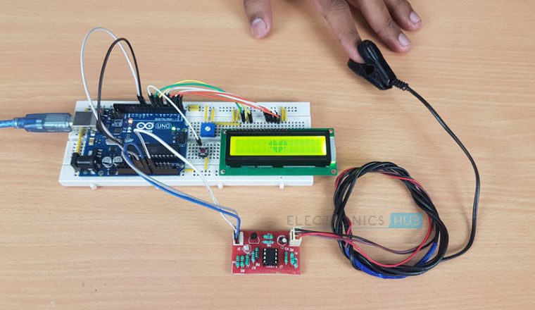
While the sensor is collecting the data, sit down and relax and do not shake the wire as it might result in a faulty values.
After the result is displayed on the LCD, if you want to perform another test, just push the rest button on the Arduino and start the procedure once again.
CODE
Applications of Heart Rate Monitor using Arduino
- A simple project involving Arduino UNO, 16×2 LCD and Heartbeat Sensor Module is designed here which can calculate the heart rate of a person.
- This project can be used as an inexpensive alternative to Smart Watches and other expensive Heart Rate Monitors.

102 Responses
hello
Is it possible to use LCD I2C?
Hello
Where is the code?
can u send me the code of this project plz
Code is uploaded.
This code is showing error’s…and
Some are red in colour which is not getting executed, kindly help me out.
the display shows the high values .what is the reason for this?
this codes also shows high values like 6k bpm. can you please tell us why and what to do to change it ?
May I know where can I buy online for Heartbeat Sensor Module with Probe (finger based)?
Hi,
Could you pls help me to get the video of “Heartbeat sensor using Arduino (Heart rate monitor)”.
Also pls let me know the step by step process for the same.
Waiting for your response.
We will upload it soon.
Hi,
Could you pls let me know the advantages of this project [Heartbeat Sensor using Arduino (Heart Rate Monitor)] over the Heartbeat using Mobile Apps??
Also how can we determine the Accuracy of this project?
Hi,
Thanks for your reply.
I have assembled components based on the mentioned circuit diagram. In addition to the mentioned circuit diagram and code, I have used 1 LED interfaced with Push button. And I have used KY-039 heartbeat sensor.
But I’m facing a problem when I press the button, It repeats the text on LCD as “Place The Finger And Press Start”.
Could you pls let me know how can this issue be solved at the earliest??
Great job! Thanks for sharing it.
I’m still waiting for you to upload the code for the robatic arm. Are you planning to share the code at any time?
Thank you,
its very nice project
its very useful.
Is it done perfectly?
can you please give me directions on where to buy the components for this project and the detailed code. thanks , awaiting your reply
Sir can u please give the step by step procedure for doing this project??
Since I have choosen this project as my bsc final year project.
Please can I get the code properly and all information about this project??
Everything is in the page: circuit diagram, components, code, connection and output video.
sir how can i find the control circuit(Based on LM358)
Which software has been used for coding?
Which software we should use??please anyone give the information please…
Arduino IDE
i know im pretty late but still…
Helo sir heartbeat sensor circuit diagram doesn’t works
Can u please upload circuit diagram beard board connection video
Its not working the heartbeat 0 bpm always , pls give us the breadboard circuit connection video!
Thank you !
anybody completed this project…..???
Connections are done but lcd is showing only black boxes..Can u say why so????
I am also experiencing this problem
Have u solved this problem ??
Sir ., Can u please explain the code.
Code is so simple
Help me to understand
Where did you get the heart rate sensor and control circuit from?
can you please explain the code….
This program can use for temperature sensor??becouse use LM358
Will this code run without any errors
If you have a similar sensor and made similar connections, then yes, the code will run without errors.
if( analogRead(data)<100) could you please explain this line
Hey,
Can you plz give the link to find these components online.
We bought most of the components from a local electronics store. Sorry, couldn’t help you.
can you please describe what this part mean in the code ?
byte customChar1[8] = {0b00000,0b00000,0b00011,0b00111,0b01111,0b01111,0b01111,0b01111};
byte customChar2[8] = {0b00000,0b11000,0b11100,0b11110,0b11111,0b11111,0b11111,0b11111};
byte customChar3[8] = {0b00000,0b00011,0b00111,0b01111,0b11111,0b11111,0b11111,0b11111};
byte customChar4[8] = {0b00000,0b10000,0b11000,0b11100,0b11110,0b11110,0b11110,0b11110};
byte customChar5[8] = {0b00111,0b00011,0b00001,0b00000,0b00000,0b00000,0b00000,0b00000};
byte customChar6[8] = {0b11111,0b11111,0b11111,0b11111,0b01111,0b00111,0b00011,0b00001};
byte customChar7[8] = {0b11111,0b11111,0b11111,0b11111,0b11110,0b11100,0b11000,0b10000};
byte customChar8[8] = {0b11100,0b11000,0b10000,0b00000,0b00000,0b00000,0b00000,0b00000};
This part of the code is responsible for the “Heart” symbol that you see on the LCD.
Pls give us Breadboard connection video
Thank you!
I want to add an enzyme device in the case of heart rate less than 67 and alarm in the case of heartbeat higher than 80 possible limit modify the code
could you pls explain me the loop of this code
I had to build the control circuit due to non availability. . But now the output heart beat is coming in the range of 2000 and above.. what could be the reason
I have the same problem, did u detect the problem ??
nothing is showing on LCD after putting program
Make sure that all the connections are correct. Check if the LCD is working with Arduino or not (like displaying “Hello World”). Try to change the Pins of Arduino (which are connected to the LCD). I assure you that the code is tested and works well.
Hello can you tell me where can buy the clip to insert finger and control circuit or heartbeat sensor? Can you email me the link please? Thank you..
Sorry. We bought the sensor (and the clip) from a local electronics store. Not sure about its online availability.
What is the store name?
Modern Electronics
why are you using count = count * 6?
We are taking the count for a period of 10 seconds. This result is being multiplied by 6 to get the beats per minute value.
ravi can you show me how to make finger clips and control circuitry? thank you
how to upload this code in ardino and what is the process.
Connect your Arduino to the computer and open Arduino IDE. Select the correct Arduino board and PORT. Type in your code and click on upload.
Hello! can anybody help me please ! I realised this project and I’m facing a problem. I used a KY 039 detector wish is made with a phototransistor and photodiode. When I place my finger in it the lcd screen shows an anormal response like 6024 BPM . I don’t know what the problem is. Give me some heeeelp pleaaaaase . Thank youuuuu
Firstly don’t use lcd, do step by step ,use ir transmitter , Photodiode, op amp lm358, led and first read about how lm358 work and it’s pin configuration then without arduino use it and after that move for lcd and arduino and if you want to see the heart beat firstly use arduino serial monitor to see the output
please how can i get the CIRCUIT diagram for the control circuit based on the LM358 and its components involved
I have already given the circuit diagram of the control circuit using LM358.
Please what are the limitations of the project
What to do if i wants to calculate data continuously without pressing the button(but measure for 10 sec when it gets a pulse) and wants to show the bpm in Android bluetooth terminal?
Where is the logic explained
Please explain the code
Sorry i need the numbers which introduce that heartbeart sensor with probe…and also the number of that controler circuit with LM358….because i want to buy them online.
What if i use KY039,do i need to change the code or to change the gain???
Is it possible to connect (join) this circuit with the temperature sensor in order to display the BPM and the value of temperature of surrounding at the same time with the same LCD????
Please i need your response…help!!!!!!!
Sir may i ask the features of this system about 4 feature please thanks it would be a huge help
Please whenever I measure the heartbeat it’s in Thousands
instead of Tens
Where can we find the heart rate sensor?
Can this work without the LM358? I connected the data pin of the sensor into A0, ground to ground and power to 5v.
Sir please can you help me out
Whenever I measure the heartbeat it’s result is always given in 6054 please kindly help me sort this very problem
WHY DID U CHOOSE FIRST OP AMP`S AMPLIFCATION FACTOR IS 1001?
IS THERE ANY SPECIFIC REASON?
How can I get this computer for making heart beat sensor.
Can not see the code
pls post
Code is already uploaded in the page. Please check it once again.
Hi
I built the circuit but it’s not working… Can you please help me with step by step process.. How to connect n wat to connect..
Waiting for your response..
sir when loading the prgm ,finding error”lcd.createChar(1, customChar1);”
Hello….i have given the circuit connection and uploaded the code but it is not working……i have used 3 pin heart rate sensor
Which software were u used for this code?
Arduino IDE.
I am using arduino uno rev 3 so in the code the is showing error how can i change it ?
Code is perfect….
Can i use KY-039 heart beat sensor?????
THERE IS NO DISPLAY
the lcd display doesn’t show anything . why this happened and also in video you say 20 k pot and required component show 10k pot.
Where is the code?
Code?
From where I will buy Heart beat sensor with probe ?
Can i use KY-039 heart beat sensor???
Sir what is the meaning of 330r resistance is it 33 ohm or 330 ohm???
TOO NICE.try attatch the code on my email please.
Hello my friend, would you show me how did you calculed the OPAM?,
Is it possible to connect or power this through a 5 v battery
Lcd display doesn’t work please send the how over come on this problem.
can anyone please explain the code…..
Hi,
Could you please upload the code of the project please or send it to me by email? I need it as soon as possible! Thanks!
if(analogRead(data)<100) stands for what?
Hi,
i have used little different heartbeat sensor(with finger probe) but did the same connection and tried to connect to the system.
The code is error free but im not able to select the port, i really dont knw wat is the problem
can anyone please suggest me wat can be the error in connection?????……..
can we get that bpm data on an android app
sir its project software based or hardware
Please provide link to purchase this kind of heart rate sensor, also provide it’s proper name to find on internet.