Ground Fault Circuit Interrupter or simply GFCI is one of the best things that has happened to the residential electrical system. You may have seen in old movies where a person accidently drops a hairdryer in the bathtub and when he/she tries to pick it up, they get electrocuted. If the outlet used in the bathroom is a GFCI, then this would never happen. That’s the beauty of GFCI. In this article, we will learn more about GFCI, how GFCI protection works, types of GFCI and also a typical GFCI Outlet Wiring explanation.
What is a GFCI?
GFCI is short for Ground Fault Circuit Interrupter. Before understanding what is GFCI and how it works, we need to first know a little bit about Ground Fault.
If you are in North America, then Black wire is hot (or live) and White wire is neutral. Bare Copper wire is used as Ground. When you plug in a device into the outlet, the mains supply flows from Black wire into the device and from the device back to the outlet and finally returns to the White wire. This is normally how current flows.
But if the current enters the device and instead of returning back to the White wire, it somehow “leaks” to ground, then this is called a Ground Fault. One of the main reasons for current taking a different path is if you touch an exposed wire or in presence of water, your body provides a path for current to flow to ground instead to taking the usual path. As the current flows through your body, you get a severe shock and depending on the intensity and duration of the shock, it might cause injury, burns or in the worst case, death.
A device that interrupts such Ground Faults and protects you from electric shock is GFCI (Ground Fault Circuit Interrupter) or sometimes known as GFI (Ground Fault Interrupter). If you are living outside North America, then such a device is known as Residual Current Device (RCD), which is usually placed in the main distribution panel and protects the entire house from such faults instead of a single outlet.
How GFCI Works?
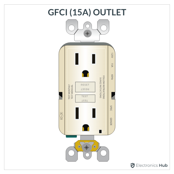
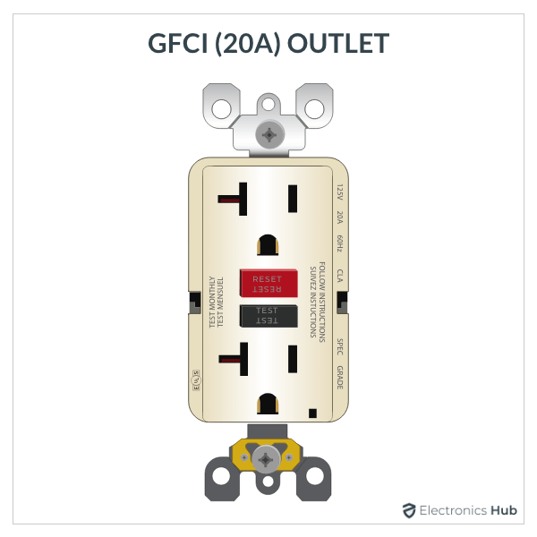
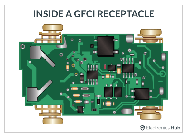
We can get to know more about GFCI by understanding how it works. So, let us see how a GFCI Outlet Works. On the outside, a GFCI outlet looks very similar, a tad bit bigger, to a regular 15A or 20A outlet, which we commonly use in our homes. But all the magic happens on the inside of a GFCI outlet or receptacle, which has some complex circuitry.
As mentioned earlier, in a 120V electrical system, the current flows from Black wire into the device / load and then returns back through the White wire. What GFCI does is it measures the current flowing to the load (from the Black wire) and also the current flowing from the load (to the White wire).
Under normal operating conditions, the current flowing to the load and that leaving the load must be the same. But if for some reason, the current is not same, the current is taking a different path other than the normal one such as flowing to the ground through your body.
This difference in current will be detected by the GFCI’s internal system and immediately opens the circuit and thus preventing an electric shock.
We can further go into the technical aspects of a GFCI by taking an abstract look at its internal circuit and understand it’s working. A typical GFCI consists of a fault sensor, a toroidal ring with pickup coil and a solenoid. When AC current flows through the magnetic toroid, it induces a voltage in the pickup coil.
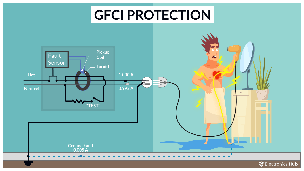
If the current flows normally through Black (hot) and White (neutral) wires, the current is equal and opposite and as a result the voltage generated (by hot and neutral) in the pickup coil will cancel out.
In case of a ground fault, some part of the current leaks to ground through your body and hence, the currents are not equal and as a result, a net voltage is induced in the pickup coil. This voltage is picked up by the fault sensor, which amplifies it and activates the solenoid. As a result, the circuit is interrupted and the flow of current stops.
Modern Class-A type GFCI Outlets can detect ground-fault currents as low as 0.005 – 0.006A (5 – 6 mA) and can trip (or shut-off) in less than 1/25 or 1/30 of a second.
Types of GFCI
GFCIs are available as either GFCI Outlets (GFCI Receptacles) or GFCI Circuit Breakers. The outlet type of receptacle type GFCI looks just like a regular outlet and can easily fit into an existing receptacle box. You can plug-in devices into these outlets and the GFCI protects from ground faults. GFCI outlets are available for 120V as well as 240V in both 15A and 20A configurations.
The breaker type GFCI or GFCI Circuit Breakers looks like normal circuit breakers and fit into the main distribution box or control panel. As a result, they can protect all the outlets connected to that breaker from ground faults. GFCI breakers are available in 20A and 30A configurations (these are more common) but you can also find 60A GFCI breakers (very rare).
Usually, the cost of GFCI breakers is significantly high and combined with the fact that you can easily reset a GFCI outlet, GFCI breakers are not that popular (you have to reset them at the main breaker panel).
Where GFCI Outlets are used?
Modern GFCI Receptacles are better than ever with complex electronic circuitry that are less prone to errors and can effectively protect you from electric shocks. As a result, the National Electric Code (NEC) requires the usage of GFCI in certain locations in a house, where the risk of electric shock is more.
Some of these locations are:
- Kitchen Countertops and Islands
- Bathrooms
- Garages
- Crawl Spaces
- Basements
- Decks, Porches and Balconies
- Wet Bars
- Laundry Sinks
- Vending Machines
- Fountains and Pools
- Outside outlets
As you can see from the list, almost all the locations mentioned here are near water or otherwise usually wet or damp.
GFCI Outlet Wiring
Even though the GFCI receptacle consists of complex electronic circuits on the inside, the external GFCI Outlet wiring is very similar to that of a standard outlet.
A typical GFCI Outlet consists of both ‘line’ and ‘load’ connections with corresponding screws and a ground connection. In order to protect people from electric shock, the GFCI outlet wiring must be done properly.
As there are both line and load connections, there are multiple ways you can wire a GFCI outlet. One way is to wire only a single GFCI Outlet and ignoring other outlets. The second way is to use a single GFCI outlet to protect multiple receptacles in the circuit. Another way is to wire a single GFCI outlet and send unprotected wired downstream. Finally, you can have a combination of protected as well as unprotected cables from a GFCI outlet.
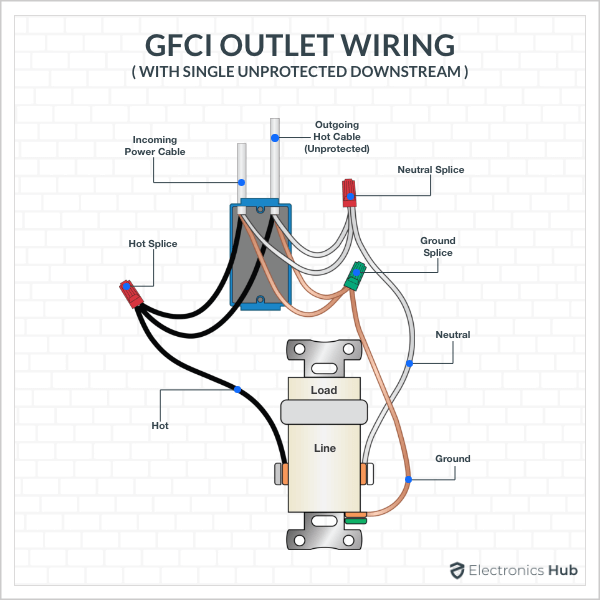
GFCI Outlet Wiring for Single Location
There are a couple of ways in which you can wire a GFCI outlet for a single location. In the first case, only the GFCI outlet exists and no other receptacles. In the second case, only the GFCI outlet is protected while the downstream circuits are unprotected.
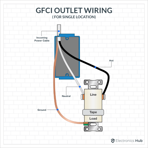
In either case, you can follow the following steps for proper GFCI Outlet Wiring.
Step 1: Disconnect the power to the receptacle at the breaker panel.
Step 2: Remove the wall cover and also take out the old receptacle from box. Do not touch the wires and test whether the power is shut-off or not with a tester. Disconnect the White (neutral), Black (hot) and Copper (ground) wires from the old receptacle.
Step 3: Connect the White wire to the terminal which is marked as “WHITE LINE” on the back of the GFCI. If it has a pigtail (for downstream circuits), connect all the White wires to the splice and connect the White pigtail wire from the splice to the White Line terminal of GFCI.
Step 4: Now, connect the Black wire to the terminal which is marked as “HOT LINE” on the back of the GFCI. If it has a splice (for downstream circuits), connect all the Black wires to the splice and connect the Black pigtail wire from the splice to the Hot Line terminal of GFCI.
Step 5: Connect the Bare Copper ground wire to the ground terminal of GFCI. If it has pigtail, you can do the same as before. Connect all ground wires to the ground splice and connect the ground pigtail wire coming from splice to GFCI’s ground terminal.
Step 6: Mount the GFCI outlet into the receptacle box and screw back the wall plate.
GFCI Outlet Wiring for Multiple Locations
Now, let us see how GFCI Outlet wiring is done for both protected and unprotected downstream receptacles. Words might not explain the wiring clearly, but you can easily understand GFCI Outlet Wiring for Multiple Locations using the following wiring demonstration diagram.
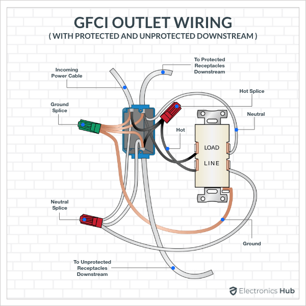
The receptacle box consists of feeder wires coming from the main breaker panel, a set of wires going to the protected downstream receptacles (from the GFCI) and another set of wires going to unprotected downstream receptacles (directly from the main breaker panel).
Step 1: Disconnect the power to the receptacle at the main control panel, take out the wall cover, unscrew the receptacle and disconnect the wires from the receptacle after testing for power with a tester.
Step 2: Connect the White neutral wire coming from the main feeder wire, the White neutral wire going to the unprotected downstream receptacles and the White neutral wire (pigtail) going to the “WHITE LINE” terminal of the GFCI to a neutral splice.
Step 3: Connect the Black hot wire coming from the main feeder wire, the Black hot wire going to the unprotected downstream receptacles and the Black hot wire (pigtail) going to the “HOT LINE” terminal of GFCI to a hot splice.
Step 4: Now, take the protected downstream circuit’s White neutral wire and connect it to the “WHITE LOAD” terminal of the GFCI Outlet.
Step 5: Similarly, connect the protected downstream receptacles’ Black hot wire to the “HOT LOAD” terminal of the GFCI Outlet.
Step 6: Now, connect all the bare copper ground wires to a single ground splice.
Step 7: Tuck away the wires and splices into the receptacle box, mount the GFCI outlet and screw back the wall cover.
Conclusion
GFCI is a life saver (literally). It protects lives from electrical shocks in bathrooms, kitchens, outdoors, where there is water and the chance of electrical shocks is higher.
In this article, we have seen what is GFCI, how a GFCI outlet works, where do you need to install GFCI outlets. We also learned about GFCI Outlet Wiring for both single location as well as multiple locations.
We hope this article helps you in understanding the GFCI a little better and make you ready to install / upgrade to GFCI outlets where ever necessary.
If you have any suggestions, tips regarding GFCI, kindly mention them in the comments. They might be helpful to other readers.
