In this tutorial, we will see some commonly used Relays. We will learn about the Classification of Relays, Different Types of Relays like Latching Relay, Reed Relay, Solid State Relay, Differential Relay, Automotive Relay, Timer Delay Relay and many more.
A Relay is a type of Switch which can switched ON or OFF with the help of a signal or a pulse of electricity. For example, if you want to turn ON or OFF and LED using a Microcontroller, you can probably connect the LED directly to the IO pin of the Microcontroller (with a current limiting resistor) and send a signal to, well, turn the LED ON or OFF.
But what if you want to turn ON or OFF a 10W mains powered LED Bulb using a Microcontroller? As the LED is a tiny device with small voltage and current requirements (which are reasonable for the Microcontroller), it is connected directly to the IO Pin of the Microcontroller.
You cannot do the same with the mains powered 10W LED Bulb. First of all, it is mains powered. And second point is that, even if it were a DC Powered Bulb, 10W is a little bit too much for the Microcontroller. This is where the devices like Relays come handy.
As mentioned earlier, in a relay, a small signal (usually from a Microcontroller) can be used to control a high voltage and high current device (like the mains powered LED Bulb mentioned before).
If you worked on DIY projects (whether for your home or on your car), you probably would have come across Relays. The Electromagnetic Relays are most popular but there are several other types of relays, used in different types of applications (industrial, automotive, etc.).
Types of Relays
There are different types of relays like:
- Electromagnetic Relays
- Latching Relays
- Electronic Relays
- Non-Latching Relays
- Reed Relays
- High-Voltage Relays
- Small Signal Relays
- Time Delay Relays
- Multi-Dimensional Relays
- Thermal Relays
- Differential Relays
- Distance Relays
- Automotive Relays
- Frequency Relays
- Polarized Relays
- Rotary Relays
- Sequence Relays
- Moving Coil Relays
- Buchholz Relays
- Safety Relays
- Supervision relays
- Ground Fault Relays
All these and many other relays are classified based on their function, application type, configuration or structural features, etc. Now, let us take a look at various types of relays, which are more popularly used in many applications.
Latching Relays
A Latching Relay is a relay which maintains its state after being actuated. That is why these types of relays are also called as Impulse Relays or Keep Relays or Stay Relays. In applications, where there is a need to limit the power consumption and dissipation, a latching relay is best suitable.
There is an internal magnet in a latching relay. When the current is supplied to the coil, it (internal magnet) holds the contact position and hence it requires no power to maintain its position. So, even after being actuated, removal of drive current to the coil cannot move the contact position but remains in its last position. Thus, considerable energy is saved by these relays.
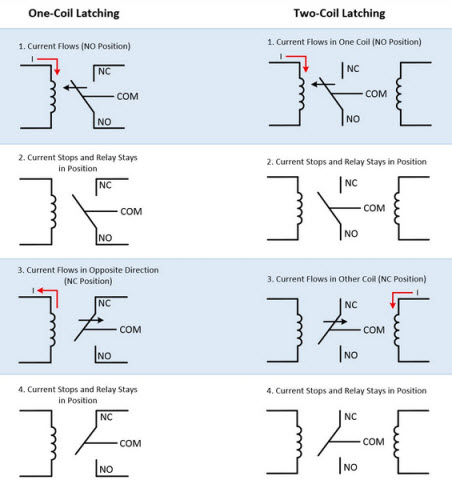
Latching relays can be made with one or two coils and these coils are responsible for the position of the armature of the relay. Hence, latching relays don’t have any default position as shown in above figure.
In one coil type relay, the armature position is determined by the direction of current flow in the coil, whereas in case of two coil type, the position of the armature is dependent on the coil in which current flows. These relays can maintain their position once they are actuated but their reset position depends on the control circuitry.
Reed Relay
Similar to the electromechanical relays, reed relays also produce the mechanical actuation of physical contacts to open or close a circuit path. However, compared with electromagnetic relays these relay contacts are much smaller and have low mass.
These relays are designed by coils wounded around a reed switch. The reed switch of the relay acts as armature and it is a glass tube or capsule filled with an inert gas within which, two overlapping reeds (or ferromagnetic blades) are hermetically sealed.
The overlapping ends of a reed consist of contacts so that input and output terminals can be connected to them. When the power is supplied to the coils, a magnetic field is produced. These fields cause reeds to drawn together, thereby their contacts make a closed path through the relay. Also, during de-energizing process of the coil, reeds are separated apart by the pulling force of spring attached to it.
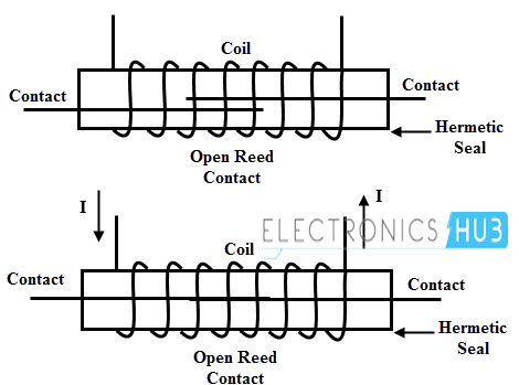
The switching speed of the reed relay is 10 times more than an electromechanical relay due to the less massive, different actuating medium and smaller contacts. However, these relays suffer from electrical arcing due to smaller contacts.
In the event of switching arc jumps across the contacts, the contact surface will melt over a small section. Further, this leads to the welding of the contacts if both contacts are still closed. Thus, even after the de-magnetization of the coil, spring force may not sufficient to separate them. It is an undesirable condition of the relay.
This problem can be overcome by placing series impedance like a resistor or ferrite between the relay and system capacitance so that inrush currents are reduced thereby avoiding any arcing in the relay. Many switching applications use the reed relay due to the small size and high speed.
Polarized Relay
As the name indicates, these relays are very sensitive to the direction of current by which it is energized. It is a type of DC electromagnetic relay provided with an additional source of permanent magnetic field to move the armature of the relay. In these relays, magnetic circuit is built with permanent magnets, electromagnets and an armature.
Instead of spring force, these relays use magnetic forces to attract or repel the armature. In this, the armature is a permanent magnet, pivoted between the pole faces formed by an electromagnet. When the current flows through the electromagnet, it produces a magnetic flux.
Whenever the force exerted by the electromagnet exceeds the force exerted by permanent magnet, the armature changes its position. Similarly, when the current is interrupted, the electromagnetic force is reduced to less than that of permanent magnet and hence armature returns to its original position.
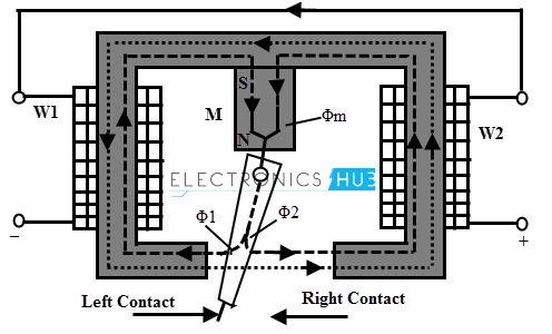
The magnetic flux Φm produced by the permanent magnet passes through the armature branches into two parts namely Φ1 and Φ2. The flux Φ1 passes through the left working gap of the magnet, while Φ2 passes through the right working gap of the magnet.
If there is no current in the coil, the armature will stay either at left or right of the neutral position due to these two fluxes, since neutral is not stable in such magnetic systems.
Whenever a current is supplied to the coils of the relay, an additional working magnetic flux Φ passes through the working gap of the magnet. Due to these magnetic field interactions, a force exerts on the armature, which depends on the magnitude of the current, initial position of the armature, polarity of the current, power of the magnet and the value of the working gap.
Depending on the combination of these parameters, the armature of the relay turns to a new stable state thereby closes the right contact and hence the relay picks up.
There are different types of polarized relays depending on the magnetic circuit configuration. The two most popular types of these relays include differential and bridge type relays.
In differential magnetic system, the difference of two fluxes of permanent magnet acts on the armature. In bridge type magnetic system, the field created by the coils divided into two fluxes which have opposite signs in the working gap area but the magnetic flux of the permanent magnet is not divided into two fluxes. For normal size relays differential type of magnetic system is widely used.
Buchholz Relays
These relays are gas operated or actuated relays. These relays are used to detect incipient faults (or internal faults which are minor faults initially but in due course of time they turn into major faults). These are most widely used for transformer protection and are accommodated in the chamber in between the transformer tank and conservator. These are used only for oil immersed relays that are majorly employed for power transmission and distribution systems.
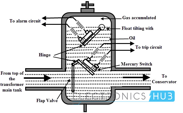
The figure above shows the operating principle of Buchholz relay. When incipient faults (or slow developing faults) occur inside the transformer, the oil level falls because of gas accumulation. This causes the hollow float to tilt and hence the mercury contacts are closed. These mercury contacts complete the path of the alarm circuit so that operator knows that there is some incipient fault occurred in the transformer.
Whenever a severe fault takes place in the transformer, such as a short circuit of phases or earth fault, etc., the pressure inside the tank is abruptly increased due to the fast reduce level of the oil. Thus, the oil is rushed towards the conductor and due to this, the lower side flap valve gets deflected. So, it closes mercury switch contacts thereby trip circuit is enabled. The transformer is then disconnected from the supply source.
Overload Protection Relays
Overload protection relays are specially designed to provide the overcurrent protection of electrical motors and circuits. These overload relays can be of different types such as fixed bimetallic strip type, electronic or interchangeable heater bimetallic, etc.
If the electric motors are overloaded, then the motors are needed to be protected from overcurrent. For this purpose, overload sensing equipment, such as heat operated relay is used. Heat operated relay consists of a coil that heats up bimetallic strip or solder pot melts and thus, releases the spring for operating auxiliary contacts which are in series with the coil. The coil gets de-energized by sensing excess current in the load due to overload.
The temperature of the motor winding can be estimated using the motor armature thermal model, electronic overload protection relay by measuring motor current. Thus, motor can be accurately protected using overload protection relay.

Solid State Relays (SSRs)
Solid state relays use solid state components such as BJTs, thyristors, IGBTs, MOSFETs and TRIACs to perform the switching operation. The power gain of these relays is much higher than the electromechanical relays because the control energy required (to power the control circuit) is much lower compared with power to be controlled (switching output) by these relays. These relays can be designed to work for both AC and DC supply.
Due to the absence of mechanical contacts, these relays have high switching speeds. A SSR consist of a sensor which is also an electronic device and this sensor responds to a control signal in order to switch on or off the power to the load.
SSRs are classified into different types, however major types of these relays include photo-coupled SSRs and transformer coupled SSRs. In transformer coupled SSR, a small DC current is supplied to the primary of the transformer through a DC to AC converter.
This current is then converted to AC and stepped-up to operate the solid-state device (TRIAC in this case) as well as triggering circuit. The degree of the isolation between the input and output depends on the design of the transformer.
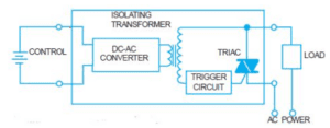
In case of photo coupled SSRs, photosensitive semiconductor device is used for performing the switching operation. The control signal is applied to the LED so that photosensitive device turns into conduction mode by detecting the light emitted from LED. The isolation provided by this type of SSR is relatively high compared with transformer coupled SSR due to the photo detection principle.

Solid state relays have faster switching speeds as compared with electromechanical relays. Also due to no moving parts, its life expectancy is higher and they tend to produce very less noise.
Also Read: What Is A Switchgear?
Inverse Definite Minimum Time Relays (IDMT Relays)
This type of relay gives a definite-time current characteristic at higher values of the fault current and an inverse time current characteristic at lower values of the fault current. These are widely used for protection of distribution lines and they offer to set the limits for current and time settings.
In this type of relay, the operating time of the relay is approximately inversely proportional to the fault current near the pickup value and becomes constant slightly above the pickup value of the relay. This can be achieved by using the core of the magnet which gets saturated for the current slightly greater than the pickup current.
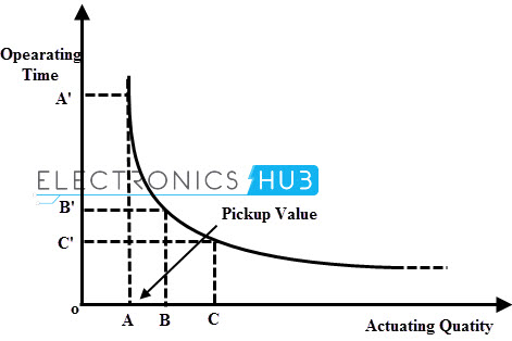
The pickup value the point where the actuating quantity or fault current initiates the relay to operate is called the pickup value. The relay is called IDMT because of its characteristic that when the actuating quantity reaches its infinity value the time doesn’t approach zero.
At lower values of the fault current, it gives inverse time characteristics while at higher values, it gives definite time characteristics as shown in figure. The operating time becomes constant from a particular value till the actuating quantity becomes infinity which is shown in the graph (a curve is obtained, which becomes constant).
Also Read: Car Horn Not Working – Causes & Quick Fixes
Differential Relays
As the name suggests, Differential Relays are those relays which work on the ‘difference’ of the controlling (or actuating) signals. Differential Relays operate when the phasor difference of two or more similar electrical quantities exceeds a predetermined value. A current differential relay operates based on the result of comparison between the magnitude and phase difference of the currents entering in and leaving out of the system to be protected.
Under normal operating condition, the currents entering and leaving are equal in magnitude and phase so the relay is inoperative. But if a fault takes place in the system, these currents are no longer equal in magnitude and phase. This type of relay is connected in such that the difference between the current entering and current leaving flows through the operating coil of the relay. Hence the relay coil is energized under fault condition due to the difference quantity of the current. Thus, the relay operates and opens the circuit breaker so as to trip the circuit.
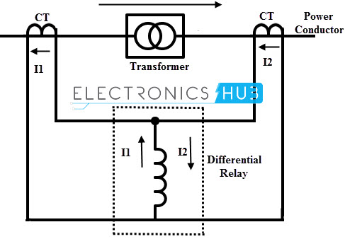
The above figure shows the principle of differential relays in which there are two CTs connected either side of the power transformer i.e., one CT on the primary side and the other at the secondary side of the power transformer. The relay compares the currents on both sides and if there is any unbalance then relay tends to operate. The differential relays can be current differential relays, voltage balance differential relays and biased differential relays.
NOTE: I will add details about more types of relays in the future.

4 Responses
Is differential relay is a static relay or not
If not then please share static type distance,overcurrent,directional and differential relay.
Super information thank you
I am using a Master Switch and Relay to switch on/off my new water harvesting SYSTEM. [Say at start of Spring] If the tank is not full – it switches on the system and will only switch off the system when the tank is full or is turned off by the master switch.
The 220V pump is controlled by its own float switch and transfers water from the sump to the collection tank when water is available.
It works fine but it leaves the relay powered until the tank is full – which could be weeks. If the summer is dry – the system could be on for 3-5 months.
Any advice on how I can arrange for the relay not to be powered when it is not needed.
Regards
Larry
Sorry – Re previous – Im using 12 or 24 V to activate the relays [I dont like using 220V in the water tank.]
Regards
Larry