This article describes the design and working of a Bidirectional Visitor Counter using 8051 Microcontroller. The main intention is to design a system wherein the number of persons entering or leaving a room is kept track of and displayed on a screen.
When a person enters the room, count would be increased, whereas on leaving, the count would decrease. IR sensing mechanism is used to sense the presence of visitors and the whole counting operation is done by a microcontroller.
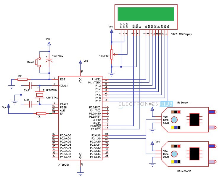
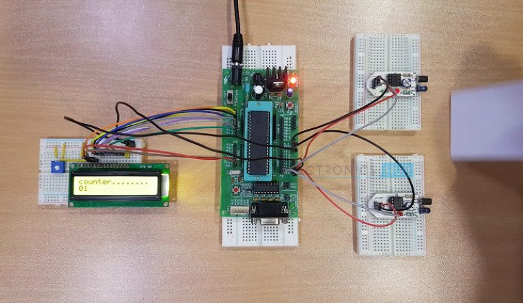
Bidirectional Visitor Counter using 8051 Microcontroller
But, before going to know about this circuit, get an idea about How to interface a 16 x 2 LCD Display to 8051 Microcontroller as we are going to use this concept in this project.
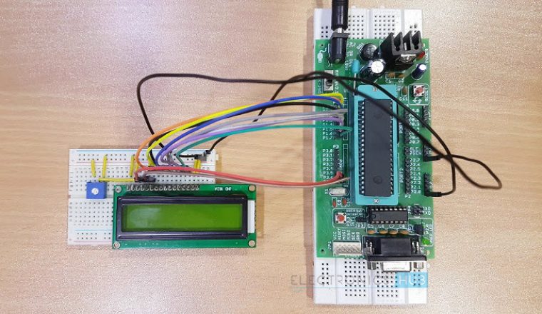
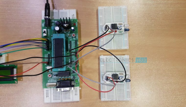
Construction and Output Video
Bidirectional Visitor Counter Circuit Principle
The circuit works on the principle of IR sensing. Infrared or simply IR Sensors are devices that work with Infrared Light Source and a Photo Detector like a Photo Diode or a Photo Transistor that act as a Transmitter and Receiver respectively.
In this project, we have used an IR LED as the IR Transmitter and a Photo Diode as the IR Receiver. Two sets of IR sensors consisting of an IR LED and Photo Diode are placed at two ends of the entrance of a room.
Output from each sensor is fed to the microcontroller. In normal operation, IR light from the LED would not fall on the Photo Diode as it is a Reflective type IR Sensor. The output from the sensor would be a logic LOW signal in this case.
In case of any interruption (due to any person crossing the path), the Photo Diode would start receiving the IR Light and start conducting. As a result, the output from the sensor would be a logic HIGH signal.
The transition from low to high, for each sensor pair is detected by the microcontroller and accordingly the count would be increased or decreased.
Do you know how to Measure Frequency using Frequency Counter?
Circuit Diagram of Bidirectional Visitor Counter
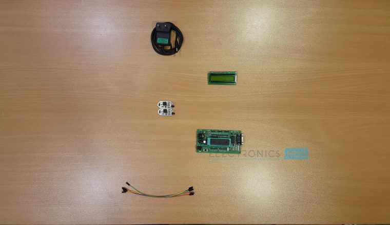
Circuit Components
Here is the list of components and their corresponding values used in this circuit. photo transistor
- AT89C51 (8051 based Microcontroller)
- 8051 Programmer
- Push Button
- 10µF Electrolytic Capacitor
- 2 x 10KΩ Resistors (1/4 Watt)
- 11.0592 MHz Crystal
- 2 x 33pF Ceramic Capacitors
- 16 x 2 LCD Display
- 10KΩ Potentiometer
- 2 x IR Sensors (Reflective Type)
- Connecting Wires
- Power Supply
- Keil µVision Software
- Willar Software
- Proteus
NOTE: A detailed circuit of the IR Sensors (Reflective Type) is mentioned in the Circuit Design section.
Related Post – 2 Digit Up/Down Counter Circuit Working and Applications

Circuit Design of Bidirectional Visitor Counter using 8051 Microcontroller
The heart of the circuit design lies in designing the Microcontroller interface. Here, we used the Microcontroller AT89C51, which is an 8051 family microcontroller.
The microcontroller AT89C51 is interfaced to the IR sensor pairs at PORT2 pins – P2.0 and P2.1 respectively. The following image shows the circuit diagram of the Reflective Type IR Sensor Module used in this project.
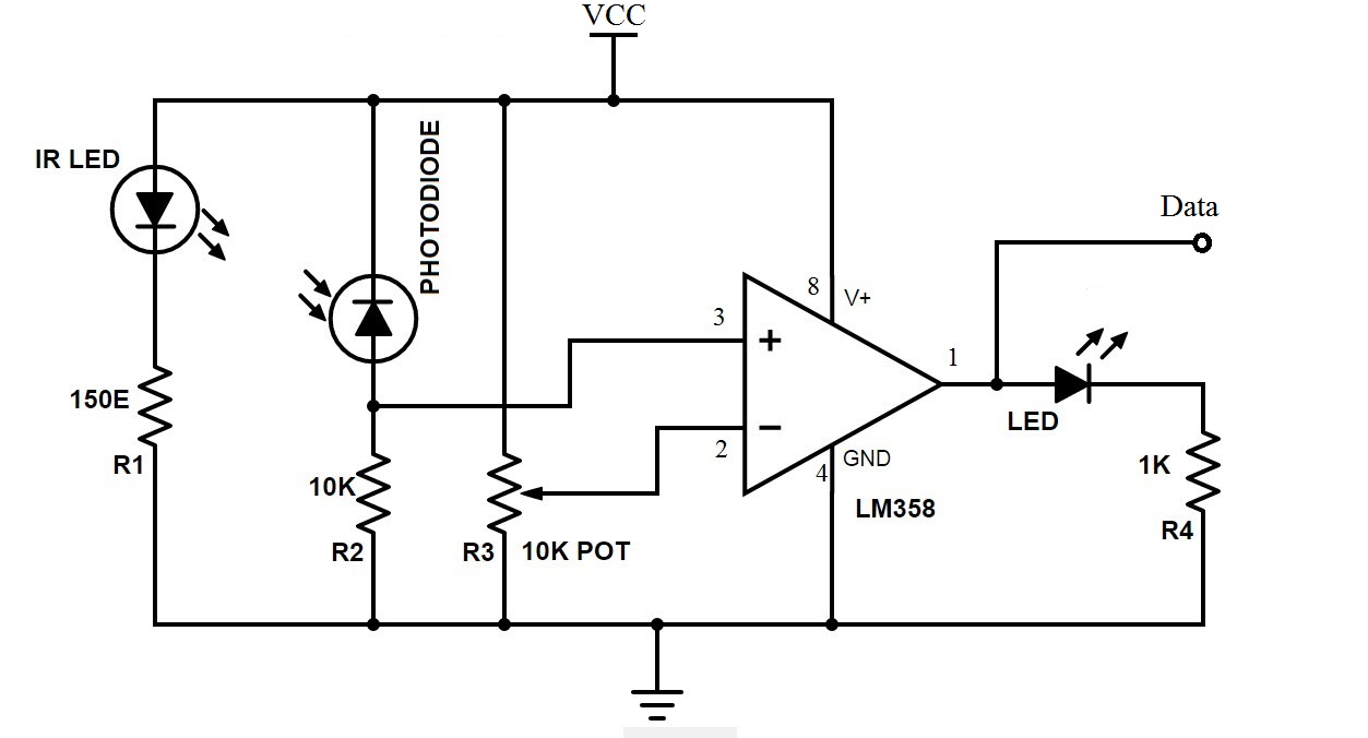
The sensor circuit is designed by selecting appropriate value of resistors for both the LED and the Photo Diode. A 150Ω current limiting resistor is placed in series with the IR LED.
Photo Diode is connected in reverse bias with a series resistor of 10KΩ. Photo Diode and 10KΩ Resistor form a potential divider and the output is given to the non – inverting input of the Operational Amplifier (Op – Amp).
A 10KΩ POT is connected at the inverting input. This POT can be adjust in order to change the sensitivity of the IR Sensor. A 16 x 2 LCD Display is used to display the count values. The data line of the LCD are connected to PORT1 Pins of the Microcontroller.
The Control Pins i.e. RS, RW and E are tied to P3.6, GND and P3.7 pins. A 10KΩ POT is connected to contrast adjust pin i.e. Pin 3 of LCD.
Another important aspect of the design involves designing the oscillator circuit and the reset circuit. The oscillator circuit is designed by selecting an 11.0592 MHz quartz crystal and two ceramic capacitors – each 33pF.
The reset circuit is designed by selecting a resistor of 10KΩ and an electrolyte capacitor of 10µF to ensure a reset pulse width of 100ms and reset pin voltage drop of 1.2V.
How to Operate Bidirectional Visitor Counter Circuit?
Let us now see hoe this Bidiractional Visitor Counter using 8051 Microcontroller actually works.
When the system is powered ON, the microcontroller initially initializes the stack pointer and all other variables. It then scans the input pins (P2.0 and P2.1).
In the meantime, when there is no object in front of the IR Sensors, the light from the IR LED would not fall on the Photo Diode of the first sensor pair and hence, the Photo Diode doesn’t conduct.
As a result, the output of the IR sensors is LOW. In other words, ports P2.0 and P2.1 are at logic LOW level. If there is a person in front of the IR Sensors, IR light from the IR LED reflects from the person and falls on the Photo Diode.
As a result, the Photo Diode starts conducting and the output of the sensor becomes HIGH. In other words, the ports P2.0 and P2.1 are at logic HIGH level.
Now when a transition takes place, i.e. a logic HIGH level is received, first at port P2.0 and then at P2.1, the microcontroller sees this as an interruption to sense the passage or entry of a person or an object in front of the IR LED and the Photo Diode.
As per the program, the count value is increased and this value is displayed on the 16 x 2 LCD Display.
If the microcontroller senses logic HIGH, first on the P2.1 and then on P2.0, it assumes that the person is leaving the room and as per the program, the microcontroller decreases the count as displays the same on the LCD.
The program ensures that the count is increased or decreased only when both the sensors detect the person.
Applications of Bidirectional Visitor Counter Circuit
- The Bidirectional Visitor Counter using 8051 Microcontroller circuit can be used domestically to get an indication of number of persons entering a party
- It can be used at official meetings.
- It can be used at homes and other places to keep a check on the number of persons entering a secured place.
- It can also be used as home automation system to ensure energy saving by switching on the loads and fans only when needed.
Limitations of this Circuit
- It is a low range circuit and cannot be implemented at large areas.
- With frequent change in the count value, after a certain time the output may look confusing.
Note: Read the post – Mini Projects for more engineering project circuits.

45 Responses
Here, the value of vcc is 5v.
it very simple and very useful to us
-thank you
Can you please share me the code?? It would be very helpful
which 7 segment display used in this project? is this common anode or common cathode??
It is common cathode display
If we use common anode does it works ….
Yes it will work but the values given to 7 segment must be changed in code..
can you give me the code of this circuit
nice work guys
what abt the code for this device?
what about the code for this device?
what about the code?
I want code for bidirectional visitor counter using led
is it the pratically constructable circuit or a rough one
can you provide me the program for this circuit
can you give me the code of this circuit
if i use two single digit 7 segment common cathode display in place of 2-Digit 7 segment common cathode display.will it work?
yess it will work
plz send code
if i use two single 7 segment common cathode displace in place of 2-Digit 7 segment common cathode display.will it work?
Which programmer we can use to code AT89c51?
plz send program code
please give the program of bidirectional visitor counter using 8051
bincybabu2013@gmail.com
please give the program of bidirectional visitor counter using 8051 microcontroller
please give the program for bidirectional visitor counter using 8051
Whare its coding
Plz give code
where is the code can somebody give me ??
please i need circuit of noise reduction
plz can anyone suggest program using 8051 microcontroller for bidirectional visitor counter
could you please provide the code of this ??
can you provide software code????
Which code is used in this project for common cathode 7 segment display?
Please send me the code
rkorbo@gmail.com
pls send me the code for this circuit
Can I get the code for this circuit?
Please send me code
can you provide the code for this project
Sir.. I am interest this project for my thesis design project.. can i get the code every parts of this project..
I can assure of proving every bit worthy of it. i will give my best to present this project to my school…
I love this project and i will like to do it in real life
how to increase sensing limit of IR sensor, like 10 feet
i am new with this project i need help please
What there are can be simulate on proteus?
What would be the detection distance in front of your sensor?
I want make this project.please help me with the code