Electrical Receptacles, Outlets, Plug-ins or whatever you call them, are an important part of every household electrical system. This is where the electricity from your main circuit breaker panel reaches for you to plug-in your TV, Dishwasher, Laptop, your smartphone and many other devices/appliances. There are several types of Electrical Outlets that serve a variety of devices but all of them have the same purpose: provide an easy and accessible way to supply power to a load. In this guide, let us take on the task of understanding the basics of an Electrical Outlet, see different types of Electrical Outlets and also a comprehensive guide on Basic Electrical Outlet Wiring Diagram.
NOTE: This is not a user guide on how to wire an electrical outlet but rather a technical discussion on Basic Electrical Outlet Wiring Diagram. If you are planning to upgrade/extend the electrical capabilities of your present setup and need installation of new outlets, then contact a licensed electrician.
Outline
ToggleA Brief Overview of an Electrical Outlet
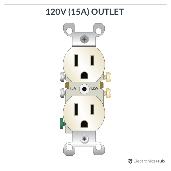
An Electrical Receptacle/Outlet is the workhorse of a house wiring as it allows you plug in various electrical appliances and provide power. The following image shows a simple layout of all the components/parts of a regular 15A 120V Duplex Receptacle.
As the name suggests, a duplex receptacle consists of two outlets to plug-in two different plugs. Each half is identical with respective neutral (long slot), hot (short slot) and ground hole (U-shaped). This receptacle ensures that the connection from plug is polarized as well as grounded for safety.
There are screw terminals and push-in fittings on the side and back to connect wires. Both sets of screw terminals (hot and neutral) are connected using a removable connecting tab. This tab allows you to wire the outlets in a variety of configurations.
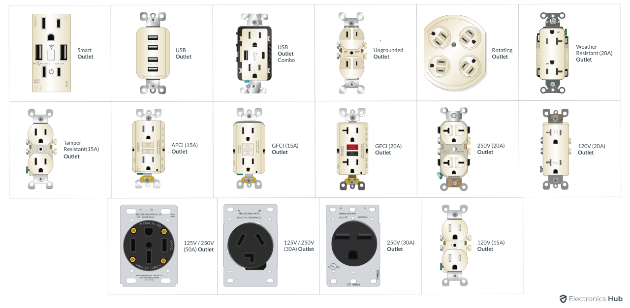
This example shows a simple 15A 120V Outlet. But we know that there are several Different Types of Electrical Outlets such as:
- 20A 120V Outlet
- 20A 250V Outlet
- 30A 250V Outlet
- 30A 125/250V Outlet
- 50A 125V / 250V Outlet7
- GFCI Outlet
- AFCI Outlet
Irrespective of the type of outlet, all the outlets essentially have the three basic screw terminals that must be properly wired to the respective wires. Some outlets may have additional terminals (for example, a 125V/250V 50A outlet has terminals for two hot wires) but the basic wiring remains the same for all outlets.
Prepare for Wiring
A proper wiring of the Electrical Outlet and installation of new receptacles is extremely important for a safe and error free operation. Many have a confusion regarding where the grounding hole goes: up or down. While there are no written rules on the “correct” way to position the outlet, many experienced electricians prefer grounding hole on the top (for a regular vertical installation).
The reason for this setup is that any object falling on top of a partially exposed plug will make contact with ground prong. If it is the other way i.e., ground hole on the bottom, then a falling object on a partially exposed plug will make contact with the hot and neutral prongs, shorting them.
In case you want to install the outlet horizontally for some reason, then make sure that the neutral slot (wide slot) is on the top. In this case, a falling object will make contact with the neutral prong of a partially exposed plug rather than the hot side. Again, this is also preferred by many electricians and is not a code/rule.
Image
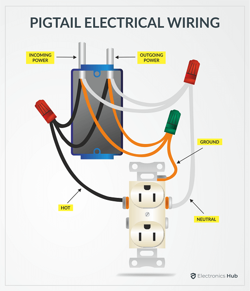
Another important thing in wiring an electrical outlet is usage of pigtails. This will help you to properly isolate one outlet to other and also easily extend wires to other downstream connections.
Image
Basic Electrical Outlet Wiring Diagram
Identify the Terminals
Let us now begin the basic electrical outlet wiring by identifying the screw terminals. There are three sets of screw terminals on the outlet:
- Brass Terminals
- Silver Terminals
- Green Terminal
The brass screw terminals are for connecting the hot wire and they are internally connected to the narrow (hot) slot of the receptacle. Silver screw terminals are for connecting the neutral wire and internally they are connected to the long (neutral) slot.
Finally, there is one green screw terminal in one corner and we use this terminal to connect the ground wire.
Types of Connection
Now, before proceeding with wiring of the electrical outlet, you need to understand the two basic types of wiring: Direct Connection and Pigtail Connection.
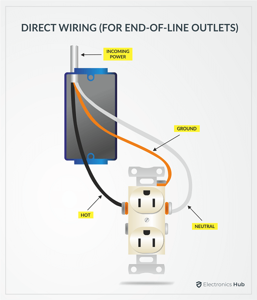
In Direct Connection, we connect the incoming wires directly to one set of screw terminals and provide a downstream connection from the other set of screw terminals.
The connecting tabs for both hot and neutral are intact in this situation. This method of wiring is not preferred as the downstream connections are dependent on this particular outlet. If you remove this wiring for any reason, then the downstream connections will lose power.
But if the outlet is last in the string, then you can go for a direct connection as there are no further downstream connections.
The preferred way of wiring is using pigtails. In this type, we form a splice from all the wires i.e., incoming, downstream and wire that connects to the screw terminal (a pigtail) using wire nuts. This is the preferred method of wiring as you can disconnect any receptacle with affecting the downstream connections
Wiring
Let us now see the actual wiring of a basic electrical outlet. We will try to showcase all the Basic Electrical Outlet Wiring Diagrams whenever necessary.
First, add pigtails for hot, neutral and ground wires from respective splices. Take the ground pigtail and loop it around the green ground screw. Try to loop the wire clock wise so that when you tighten the screw, the screwhead will grip the wire firmly.
Now, take the white neutral pigtail and strip about 1inch of the insulation. Insert the exposed wire from the front into the silver screw terminal until it just protrudes from the slot. Now loop the wire around the screw and tighten the screw.
Flip the outlet and it gives you access to the brass screw terminals. Repeat the same process for hot (black) wire i.e., strip about 1inch of insulation, insert the exposed wire into the brass screw terminal until it just protrudes from the slot, loop the wire around the screw and tighten the screw.
Now, push all the wires carefully in to the receptacle box and neatly bend the wires if necessary. If you are folding the wires to insert them into the box, then follow this order: first bend and push the ground wires, then bend and push the neutral wires and finally bend and push the hot wires.
Once you tuck in all the wires neatly, push the outlet into the box and secure it with screws.
This example covers the Basic Electrical Outlet Wiring Diagram. You can further make several types of connection by breaking the tabs on the hot side to connect the two outlets to two different hot wires, connect two hot wires for 240V 50A heavy duty outlets and many more.
Conclusion
Electrical Outlets or Receptacles are very important for using our electrical appliances. Hence, it is essential that we wire them properly for safety. We saw the basics of an electrical outlet, the important parts of a regular 120V 15A Duplex Outlet, different types of wiring strings and also a Basic Electrical Outlet Wiring Diagram.


