The Water Level Indicator employs a simple mechanism to detect and indicate the water level in an overhead tank or any other water container.
The sensing is done by using a set of nine probes which are placed at nine different levels on the tank walls (with probe 9 to probe 1 placed in increasing order of height, common probe (i.e. a supply carrying probe) is placed at the base of the tank). The level 8 represents the “tank full” condition while level 0 represents the “tank empty” condition.
Recommend Reading: How Water Level Controller Circuit Works using 8051 Microcontroller?
When the water-level is below the minimum detectable level (MDL), the seven segment display is arranged to show the digit 0, indicating that the tank is empty, when the water reaches level1 (but is below level2) the connection between the probes gets completed (through the conducting medium – water) and the base voltage of transistor increases.
This causes the base-emitter junction of transistor to get forward biased, this switches transistor from cut-off to conduction mode thus PIN (B7) of microcontroller is pulled to ground hence, the corresponding digit displayed by the seven segment display is 1.
The similar mechanism applies to the detection of all the other levels. When the tank is full, all input pins of microcontroller become low. This causes the display to show 8 and also in this case a buzzer sound is given, thereby indicating a “tank full” condition.
Most water level indicators are equipped to indicate and detect only a single level. The Water Level Indicator implemented here can indicate up to nine such levels and the microcontroller displays the level number on a seven segment display.
So, the circuit not only capable of cautioning a person that the water tank has been filled up to certain level, but also indicates that the water level has fallen below the minimum detectable level. This circuit is important in appliances such as the water cooler where there is a danger of motor-burnout when there is no water in the radiator used up also it can be used in fuel level indication.
Recommened Reading: Water Level Alarm Using 555 Timer
In this project we show the water level indicator using eight transistors which conducts as level rises, a buzzer is also added which will automatically start as the water level becomes full, auto buzzer start with the help of microcontroller. With the help of this project we not only show the level of water on seven segment display but also indicate the water full condition using a buzzer.
Water Level Indicator Project Circuit Features:
- Easy installation.
- Low maintenance.
- Compact elegant design.
- The Automatic water level controller ensures no overflows or dry running of pump there by saves electricity and water.
- Avoid seepage of roofs and walls due to overflowing tanks.
- Fully automatic, saves man power.
- Consume very little energy, ideal for continuous operation.
- Automatic water level controller provides you the flexibility to decide for yourself the water levels for operations of pump set.
- Shows clear indication of water levels in the overhead tank.
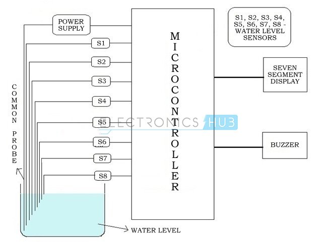
Water Level Indicator Project Block Diagram:
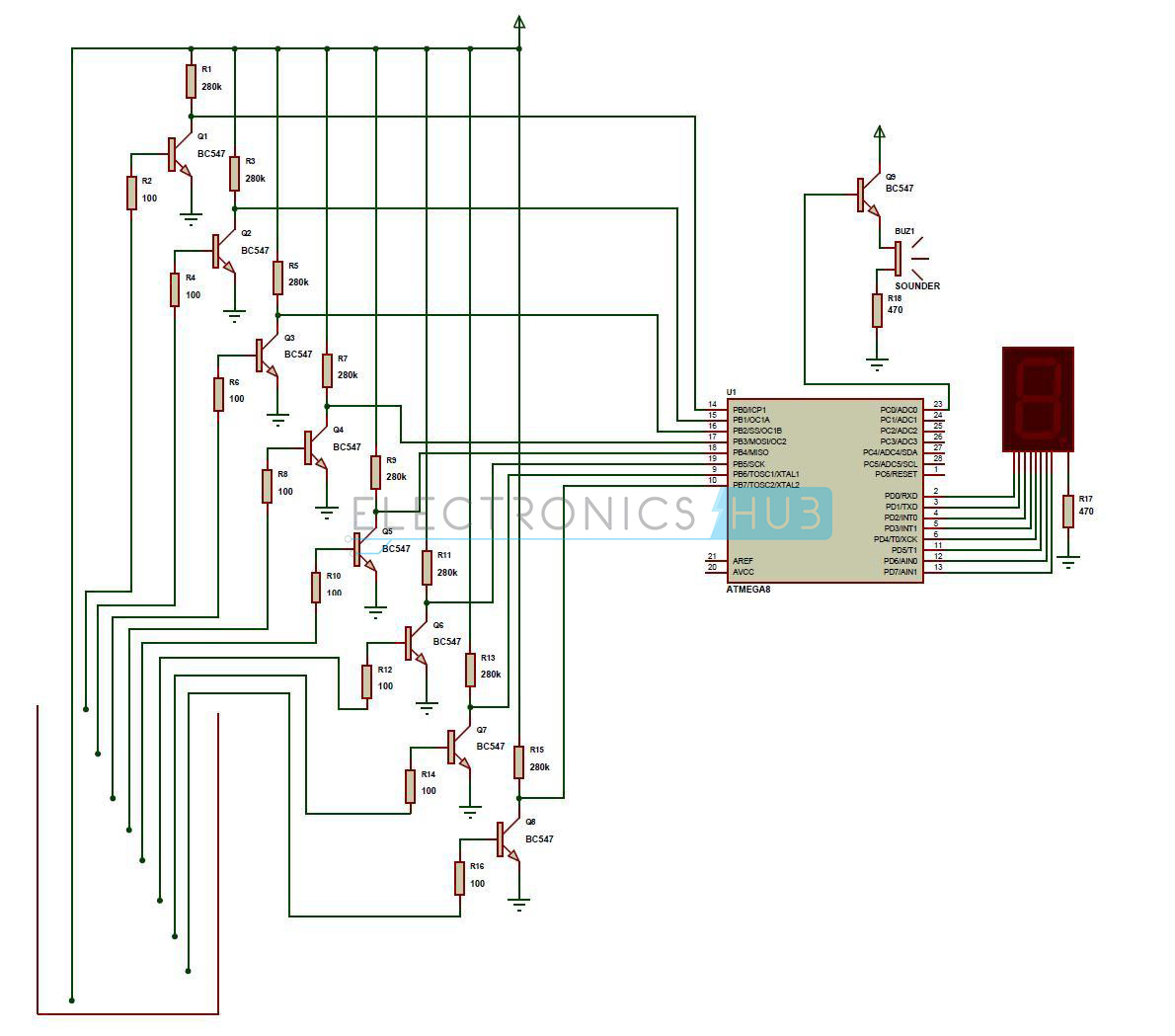
Water Level Indicator Circuit Diagram:
Download Project Code
How to Design Water Level Indicator Project using AVR Microcontroller?
- A constant 5v power supply is given to the microcontroller and rest of the circuit from a battery.
- The tank has 9 conductive type sensors (other types of sensors have been mentioned earlier but in our project only conductive type are used) embedded into it and 8 wires of sensors out of 9 are connected to transistors and the 9th is connected to 5v+ supply.
- The use of transistor is it acts as inverter (i.e. in on state gives low voltage at output and in non conducting state gives high voltage at its output), all transistors outputs are connected to PORTB of microcontroller.
- Seven segment display is connected to PORTD. It is connected in common cathode fashion.
The Output for the 7th level is not only shown on seven segment display but also indicated with a discontinuous buzzer sound. - Output for the 8th level (i.e. tank full condition) is not only shown in seven segment display but also indicated with a continuous buzzer sound.
How Water Level Indicator Project Circuit Works?
The operation of this project is very simple and can be understood easily. In our project “water level indicator” there are 3 main conditions:
- There is no water available in the source tank.
- Intermediate level i.e. either of 3rd to 7th level.
- There is ample amount of water available in the source tank.
So let us discuss more about these 3 conditions
CONDITION 1: Water not available
When the tank is empty there is no conductive path between any of the 8 indicating probes and the common probe (which is connected to 5v+ supply) so the transistor base emitter region will not have sufficient biasing voltage hence it remains in cut off region and the output across its collector will be Vc approximately 4.2v.
As in this case the microcontroller is used in the active low region (which means it considers 0-2 volts for HIGH and 3-5 volts for LOW) now the output of transistor which is 4.2v approximately will be considered as LOW by the microcontroller and hence the default value given by microcontroller to the seven segment display is 0 which indicates as the tank is empty.
CONDITION 2: Intermediate levels
Now as the water starts filling in the tank a conductive path is established between the sensing probes and the common probe and the corresponding transistors get sufficient biasing at their base, they starts conducting and now the outputs will be Vce (i.e. 1.2v-1.8v) approximately which is given to microcontroller.
Here the microcontroller is programmed as a priority encoder which detects the highest priority input and displays corresponding water level in the seven segment display.
In this project while the water level reaches the 7th level i.e. last but one level along with display in seven segment a discontinuous buzzer is activated which warns user that tank is going to be full soon.
CONDITION 3: Water full
When the tank becomes full, the top level probe gets the conductive path through water and the corresponding transistor gets into conduction whose output given to microcontroller with this input microcontroller not only displays the level in seven segment display but also activates the continuous buzzer by which user can understand that tank is full and can switch off the motor and save water.
Water Level Indicator Project Working Flow Chart:
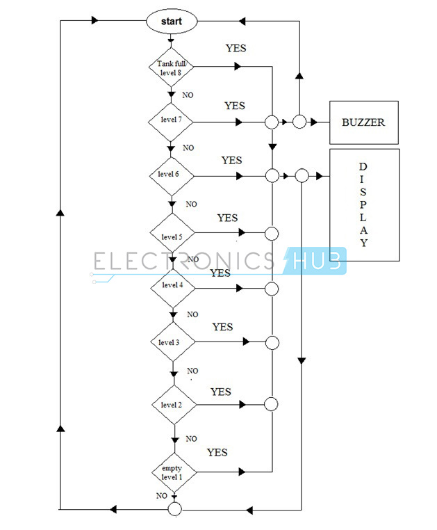
Flow chart gives the clear and easy understanding of the project. The process goes on as follows:
The microcontroller checks for tank full condition, if the condition is satisfied it indicates the same on display unit and also sounds a buzzer if the condition fails it checks again and this process continues and the corresponding level is indicated in the display unit.
Recommend Reading – How to Interface Seven Segment Display to 8051 Microcontroller?
Water Level Indicator Project Applications:
- Automatic Water level Controller can be used in Hotels, Factories, Homes Apartments, Commercial Complexes, Drainage, etc., It can be fixed for single phase motor, Single Phase Submersibles, Three Phase motors. (For 3Æ and Single Phase Submersible Starter is necessary) and open well, Bore well and Sump. We can control two motor and two sumps and two overhead tanks by single unit.
- Automatic water level controller will automatically START the pump set as soon as the water level falls below the predetermined level (usually 1/2 tank) and shall SWITCH OFF the pump set as soon as tank is full.
- Fuel level indicator in vehicles.
- Liquid level indicator in the huge containers in the companies.
We are providing complete information i.e circuit diagram and project code here, it would be great if you can share some of your project details with us.
Here, you can check the complete out put video of water level indicator. Hope this will helps you to get clear idea. Get latest electronics projects updates by visiting this site regularly.

48 Responses
hello i wonder if i can get the source Code for this project..
we have updated the project code. you may check now.
hi brother i am making this project for my home can you please help me i am struck in programming my Micro-controller
Please Help
Is it possible to operate it as manually also…
your question seems incomplete. but if you wish to do this project without microcontroller, this link might help you – https://www.electronicshub.org/water-level-alarm-using-555-timer/
I ALSO REQUIRE IT…PLZ GET IT N TELL ME…
I am interested of this water level controller.. So please sir tell me about this thing that how can i make it for my personal project………..
hello Good day ! .. what kind of microcontroller is being used here ? specifications ? thanks
atmega8
Hello, i’m trying to make a project similar to this one using sensor probes however i would like to connect the output (level of the water) to the raspberry pi in order for it to display on an LCD the current water level
Hi Elliot,
I am also looking to work on similar project where I can connect the water sensors to raspberry pi and collect the data. can you please help me how can implement it.
Thanks
Kal
gr8.kal@gmail.com
Hello sir…I want to make this project “Water Level indicator”. Which micro controller is used for it?
And are we require to program this micro controller for this project? And if it require then how it does?
10q for ur project
sir, i would like to know and very much interest in it. please mail it now sir,
Nice
please,can i get the code of this project by using 8051 micro controller? thank you
sir can u tell me what type of transistors should be used with their numbers
what are the components required for this project
answer please sir!!!
i did project on automatic water level indication of dam gate control system by using voice ic and buzzer.in that we used three wires for indicating the water levels in the gam. if the water level is reached the first wire the output will be as “water level is low” this will display on lcd and this will come in the form of voice also.if water level reaches the second wire then output is”water level is medium” and at third level output is”water level is high”.my question is…….
1.in what form the information from water through wire is going to the microcontroller?
please mail me sir answer as possible as.
and if any one knows can mail me… thanks
in water level indication of dam gate control system by using voice ic and buzzer project if water level indication from the water through wire is comming to microcontroller …in what form that information is going to microcontroller?
the people who knows answer please mail me with explanation.
thanks for the details,
Do you think that there can be any higher level ,situation of this project.As it seems easy to implement this.
hi. can i get the full write up of the project if possible
Pls i want a programme of water level indicator using vhdl
Urgent h plsss help me
Sir can i know why only specific measurements of components are used ? What if different measurements of components aŕe used
I hd this project in my college as bathfull indicator i hv cmpleted d project i required d info bt i gt it here itself ty fr ur help
It had a simple circuit costing me only 50 rupees
Ur info cmpleted my project report
sir please give the FSMD diagram and psm code of this water level indicator urgent
please send project on automatic toilet cleaning system
it is very useful
it is very interesting topics
Where is the connect power supply plz show in diagram
There is a arrow mark in the diagram it represents the vcc.
Eѵеrything is very open with a precise clarification of the
challenges. It was definitely informative. Your site
is useful. Thаnks f᧐r ѕharing!
Hi, what kind of sensors can I use?
it is very useful to gothrough our knowledge
hello sir which type of microcontroller is used for it.
Hey,
Really interested in this and I’m using a KL43Z board and was wondering how to do like if there’s a source code for this
Really need HELP !!!
I wonder if anyone tell me the software name to run this program.Thank you.
why dont you just connect the probes directly to the micro-controller?
In general yes you can. but, it should not exceed the current rating of the microcontroller GPIO Pins (40mA). Here in our case the current will be more than 40mA if you connect it directly from the water tank. that is why here we are using a transistor with a current limiting resistor to protect the controller from high current.
If you wanna know more on how to use NPN transistor then you should consider reading this – https://www.electronicshub.org/npn-transistor/
Hello sir ..I’m interested with your project and wish to implement it in my home .Help me get the source code to make it work appropriately ,I’ll be grateful for your help .
Please try to read the article completely, because the link was already given.
anyways, I hope this link will help you – https://www.electronicshub.org/wp-content/uploads/2015/05/Water-Level-Indicator.zip
Thanks for sharing the water level indicator for real time. Now I can submit this final year project. Many many thanks. Keep posting helpful and useful material posts.
Can you please help me with everything you used for this project, I am currently working on it as my final year project.
I am wondering if those probe corrode due to electrolysis
Can you please tell me the clear explanation what microcontroller is been used n what components are used
– 1 x Atmega8 Microcontroller
– 9 x BC547 NPN Transistor
– 8 x 100Ω Resistor
– 8 x 280KΩ Resistor
– 2 x 470Ω Resistor
– 1 x 7 Segment Display (Common Anode)
– 1 x 5v Buzzer
Hello ,
Thanks for this design. I implemented it It works well. Since this project is Battery operated (in my case), Input transistor switches if closed would consume current all the time.
So I added another transistor to switch ON power to common probe. So I just turn on power to common probe then read inputs then turn off. This saved power of my Battery which is solar powered. This is just a tip..
Your project has one problem with long term use. Constant potential electrodes corrode over time.